
Side-light type backlight module and liquid crystal display device

A backlight module, edge-lit technology, applied in lighting devices, fixed lighting devices, components of lighting devices, etc., can solve the warping of the light guide plate, the expansion and contraction of the light guide plate cannot be fully absorbed, and has no buffering properties. and other problems to achieve the effect of avoiding warping and avoiding cracking of the light guide plate

Active Publication Date: 2012-07-11
SHENZHEN CHINA STAR OPTOELECTRONICS TECH CO LTD
View PDF8 Cites 16 Cited by
  • Summary
  • Abstract
  • Description
  • Claims
  • Application Information

AI Technical Summary

Problems solved by technology

[0002] The current mass-produced edge-lit backlight modules need to use a light guide panel (Light Guide Panel). Since the coupling distance between the light source of the backlight module and the light guide panel is relatively accurate, the installation of the light guide panel tends to be rigid. The positioning column or the right-angle positioning edge, however, the light source of the backlight module will emit heat when it is working, which will heat up the light guide plate and heat up. Since the positioning column and the right-angle positioning edge are made of rigid materials and have no cushioning properties, it may cause The following problems: First, the expansion and contraction of the light guide plate cannot be fully absorbed, which may easily cause warping and deformation of the light guide plate; second, the light guide plate is in rigid contact with the positioning structure, and it is easy to cause the light guide plate to break when it is hit

Method used


Image

  • Side-light type backlight module and liquid crystal display device
  • Side-light type backlight module and liquid crystal display device
  • Side-light type backlight module and liquid crystal display device

Examples


Embodiment Construction

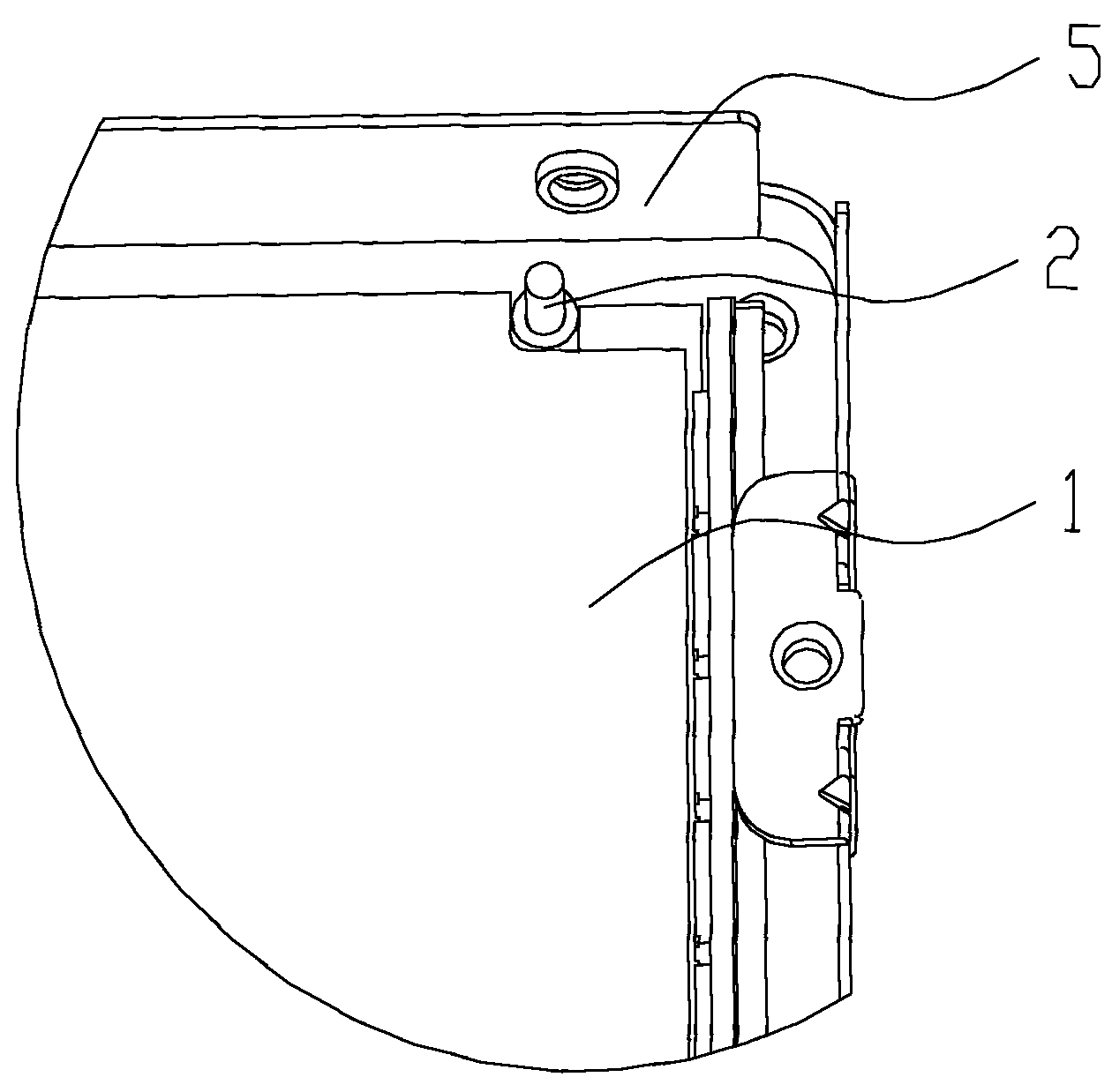
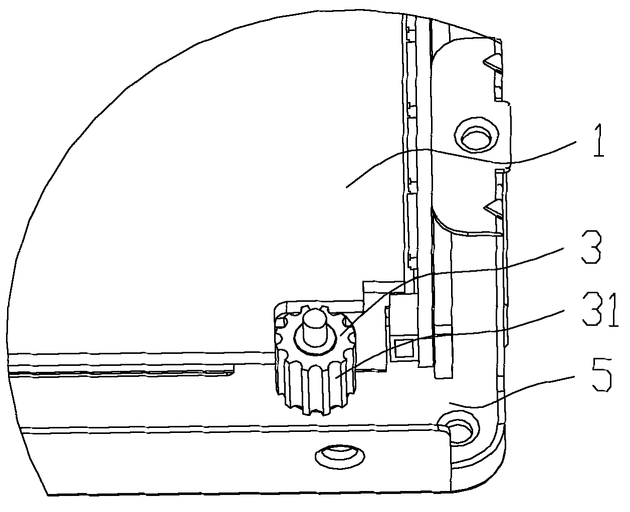
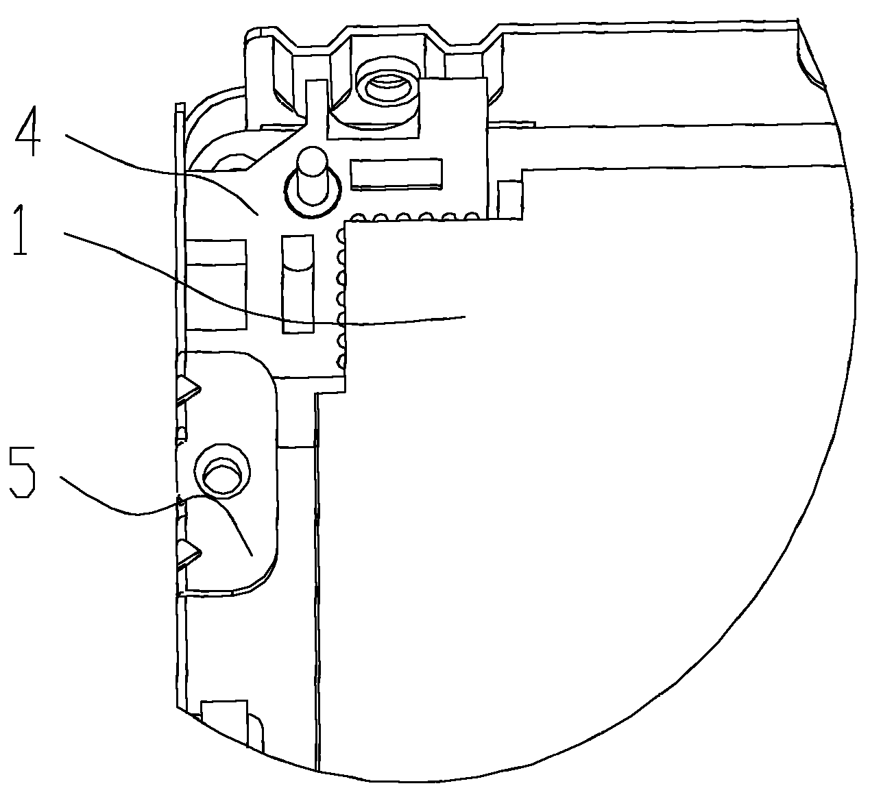
[0025] The invention discloses a side-light backlight module and a liquid crystal display device, the liquid crystal display device includes a side-light backlight module, as an embodiment of the side-light backlight module of the present invention, such as Figures 1 to 4 As shown, the edge-lit backlight module includes a light guide plate 1 and a positioning member for positioning the light guide plate 1. The light guide plate 1 is rigidly positioned in the direction toward the light source and buffered in other directions.

[0026] The side-light backlight module and the liquid crystal display device of the present invention adopt a new positioning structure of the light guide plate. 1 Rigid positioning in the direction towards the light source can control the light coupling distance between the light guide plate and the light source of the side-light backlight module to obtain a better light guiding effect; and buffer positioning in the other directions to absorb The amoun...


PUM


Abstract

The invention belongs to the field of liquid crystal display, and particularly relates to a side-light type backlight module and a liquid crystal display device. The side-light type backlight module comprises a light guide plate and a positioning part for positioning the light guide plate, and the light guide plate is rigidly positioned in a direction facing a light source and is positioned in a cushioned manner in the rest directions. The side-light type backlight module and the liquid crystal display device use a novel light guide plate positioning structure, as the light guide plate is rigidly positioned in the direction facing the light source, the light coupling distance between the light guide plate and the light source of the side-light type backlight module can be controlled to obtain fine light guide effect, and the light guide plate is positioned in the cushioned manner in the rest directions, so that expansion and contraction of the light guide plate are absorbed to avoid warping and deformation of the light guide plate. Besides, the light guide plate can be prevented from breaking due to rigid contact of the light guide plate and the positioning structure in impact.

Description

technical field [0001] The invention belongs to the field of liquid crystal display, and more specifically relates to a side-light type backlight module and a liquid crystal display device. Background technique [0002] The current mass-produced edge-lit backlight modules need to use a light guide panel (Light Guide Panel). Since the coupling distance between the light source of the backlight module and the light guide panel is relatively accurate, the installation of the light guide panel tends to be rigid. The positioning column or the right-angle positioning edge, however, the light source of the backlight module will emit heat when it is working, which will heat up the light guide plate and heat up. Since the positioning column and the right-angle positioning edge are made of rigid materials and have no cushioning properties, it may cause The following problems: first, the expansion and contraction of the light guide plate cannot be fully absorbed, which may easily cause...

Claims


Application Information

Patent Timeline
Patent Type & Authority Applications(China)
IPC IPC(8): F21S8/00F21V8/00F21V17/10G02F1/13357
CPCG02B6/0088G02B6/0093G02F1/133608G02F1/133F21V17/10F21S8/00
Inventor 张彦学
Owner SHENZHEN CHINA STAR OPTOELECTRONICS TECH CO LTD
Learn More