Pre-combustion mechanical grate decoupling combustion furnace and combustion method for same

A technology of mechanical furnace and combustion furnace, which is applied in the field of pre-combustion mechanical grate decoupling combustion furnace and its combustion, which can solve the problems of interruption of combustion, difficulty in greatly increasing the combustion load of pre-combustion chamber, and slow pre-combustion speed. Ensure stable and continuous operation, reduce the effect of decoupling combustion, and avoid the effect of combustion interruption

Active Publication Date: 2012-07-11
INST OF PROCESS ENG CHINESE ACAD OF SCI
View PDF8 Cites 22 Cited by
  • Summary
  • Abstract
  • Description
  • Claims
  • Application Information

AI Technical Summary

Problems solved by technology

However, it is still difficult to effectively control the pyrolysis rate of the oxidation pyrolysis chamber located above the mechanical grate, which leads to a poor match between the pre-combustion load and the main combustion load
The Chinese patent application with the publication number CN101650025 proposes a new decoupling combustion furnace and decoupling combustion method. Although the problem of the slow pyrolysis speed of the previous decoupling combustion boilers has been solved to a large extent, the pre-combustion The fire zone and the main combustion zone share a set of grate control mechanism, and there is no measure to maintain the pre-combustion fire source, and the pre-combustion speed is slow. When the load is large and the grate running speed is increased, the ignition source cannot be maintained in the pre-combustion zone. Live, it will be moved to the main combustion area by the grate, resulting in the interruption of combustion in the pre-combustion area, and finally the main combustion cannot be maintained, resulting in interruption of combustion
Therefore, in this scheme, it is difficult to greatly increase the combustion load of the pre-combustion chamber, so it can only meet the design requirements of small and medium-sized boilers with a capacity of less than 10t / h

Method used


Image

  • Pre-combustion mechanical grate decoupling combustion furnace and combustion method for same
  • Pre-combustion mechanical grate decoupling combustion furnace and combustion method for same
  • Pre-combustion mechanical grate decoupling combustion furnace and combustion method for same

Examples


Embodiment Construction

[0035] Hereinafter, the present invention will be further described in conjunction with the accompanying drawings and embodiments.

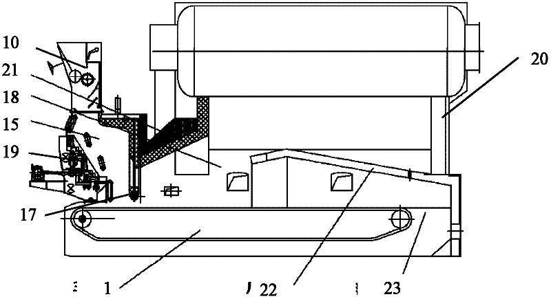
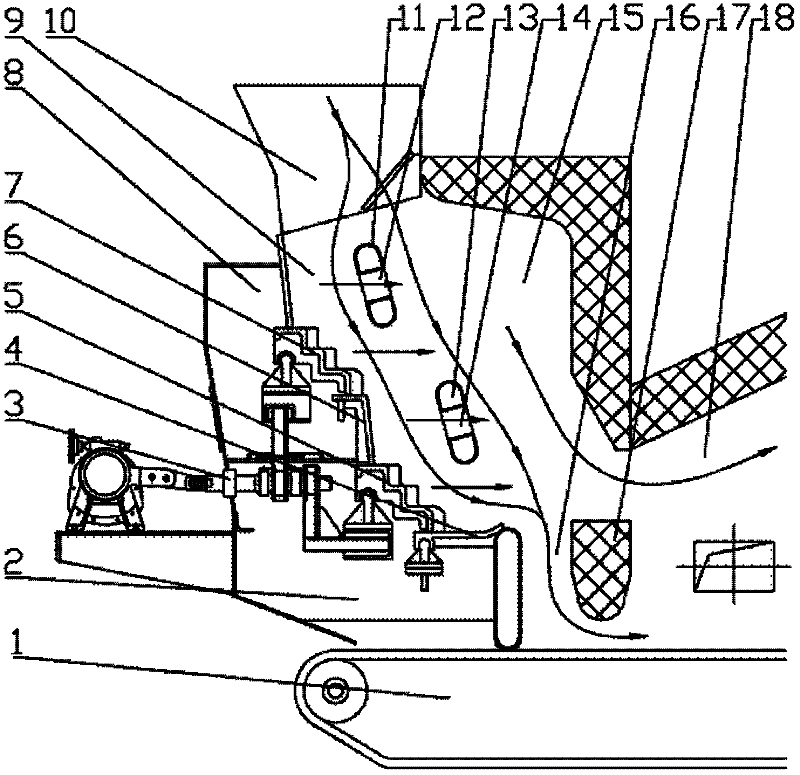
[0036] According to one embodiment of the present invention, a pre-combustion mechanical grate decoupling combustion furnace is provided, such as figure 1 As shown, the decoupled combustion furnace includes: a layered coal feeding device 10 , a furnace body 20 , a combustion chamber partition wall 17 , a main grate 1 and a pre-combustion grate 19 . In the present invention, the furnace body can directly adopt various specific structures of industrial boilers in the prior art, for example, the furnace body can include a front arch 21 and a rear arch 22, and the specific structure of the furnace body will not be repeated here. The inside of the furnace body is provided with a combustion chamber partition wall 17 , which generally divides the inner space of the furnace body into an upstream pre-combustion chamber 15 and a downstream main combustion ...


PUM


Abstract

The invention provides a pre-combustion mechanical grate decoupling combustion furnace, which comprises a furnace body, a main grate (1) and a pre-combustion grate. A combustion chamber division wall (17) is arranged inside the furnace body, the internal space of the furnace body is generally divided into an upstream pre-combustion chamber (15) and a downstream main combustion chamber (18), the main grate (1) is arranged on the lower portion of the furnace body, the pre-combustion chamber (15) is positioned above the front of the main grate (1), the main combustion chamber (18) is positioned above the rear of the main grate (1), the pre-combustion chamber (15) is communicated with the main combustion chamber (18) through a flue gas channel above the division wall (17) and a coal bed channel below the division wall (17), and the pre-combustion grate is positioned in the pre-combustion chamber (15) and is arranged above the main grate (1) by a certain inclination angle, so that a coal bed runs to the main grate (1) along the pre-combustion grate. By the aid of the pre-combustion mechanical grate decoupling combustion furnace, pre-combustion load can be effectively matched with main combustion load, and the problem of flameout can be avoided while the running load of the decoupling combustion furnace is improved.

Description

technical field [0001] The invention relates to the field of coal combustion equipment, in particular to a pre-combustion mechanical grate decoupling combustion furnace and a combustion method thereof. Background technique [0002] The total number of coal-fired industrial boilers in my country is about 550,000, with an annual coal consumption of nearly 500 million tons. They mainly use layer combustion and most of them are chain furnaces. There are common problems such as low combustion efficiency and high pollutant emissions. Among them, nitrogen oxides (NOx) emitted by industrial boilers x ) accounted for NO in my country x 15% to 20% of the total emissions. Therefore, it is necessary to develop relevant emission reduction technologies to reduce the NOx of industrial boilers x emissions. [0003] Low NO for coal-fired industrial boilers x Combustion technologies mainly include low-oxygen combustion technology, flue gas recirculation combustion technology, air staged ...

Claims


Application Information

Patent Timeline
Patent Type & Authority Applications(China)
IPC IPC(8): F23B10/02
Inventor 郝江平高士秋李静海白健康尚校蔡连国许光文
Owner INST OF PROCESS ENG CHINESE ACAD OF SCI
Why Eureka
Try Eureka