In-place gas measurement method and in-place gas measurement device

A gas measurement and gas technology, which is applied in the field of on-site gas measurement, can solve problems such as instability and large measurement errors, and achieve the effect of small measurement errors and stable measurement optical path

Active Publication Date: 2012-07-11
FOCUSED PHOTONICS
View PDF14 Cites 6 Cited by
  • Summary
  • Abstract
  • Description
  • Claims
  • Application Information

AI Technical Summary

Problems solved by technology

However, the flow rate of the gas to be measured in the process pipeline is generally not fixed, and the changing fl

Method used


Image

  • In-place gas measurement method and in-place gas measurement device
  • In-place gas measurement method and in-place gas measurement device
  • In-place gas measurement method and in-place gas measurement device

Examples


Example Embodiment

[0040] Example 1:

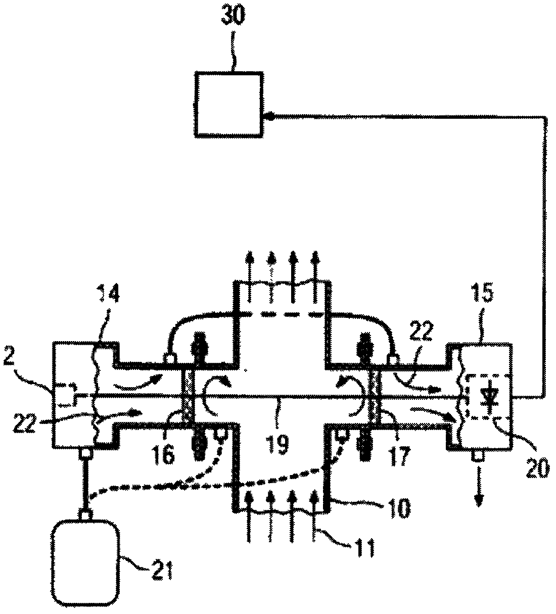
[0041] figure 2 The basic structure diagram of the on-site gas measuring device according to the embodiment of the present invention is schematically given. Such as figure 2 As shown, the gas measuring device includes:

[0042] Laser and driving circuit 2, detector 20, analysis unit 30 and purge unit 21. Windows 16 and 17 are provided on the measuring channel to isolate the process gas 11.

[0043] The gas interfaces 23, 24 are respectively arranged at the first gas discharge pipe 10 provided by the purge unit 21 for allowing the second gas to pass through the interface and follow the process in the pipe The flow direction of the gas 11 is discharged into the pipeline, thereby forming a gas wall separating the first gas and the process gas, and maintaining the stability of the measurement optical path between the two gas walls; preferably, the width of the gas interface is [0.1mm, 1.0mm].

[0044] A gas supply unit 22, the gas supply unit 22 is used to supply ...

Example Embodiment

[0056] Example 2:

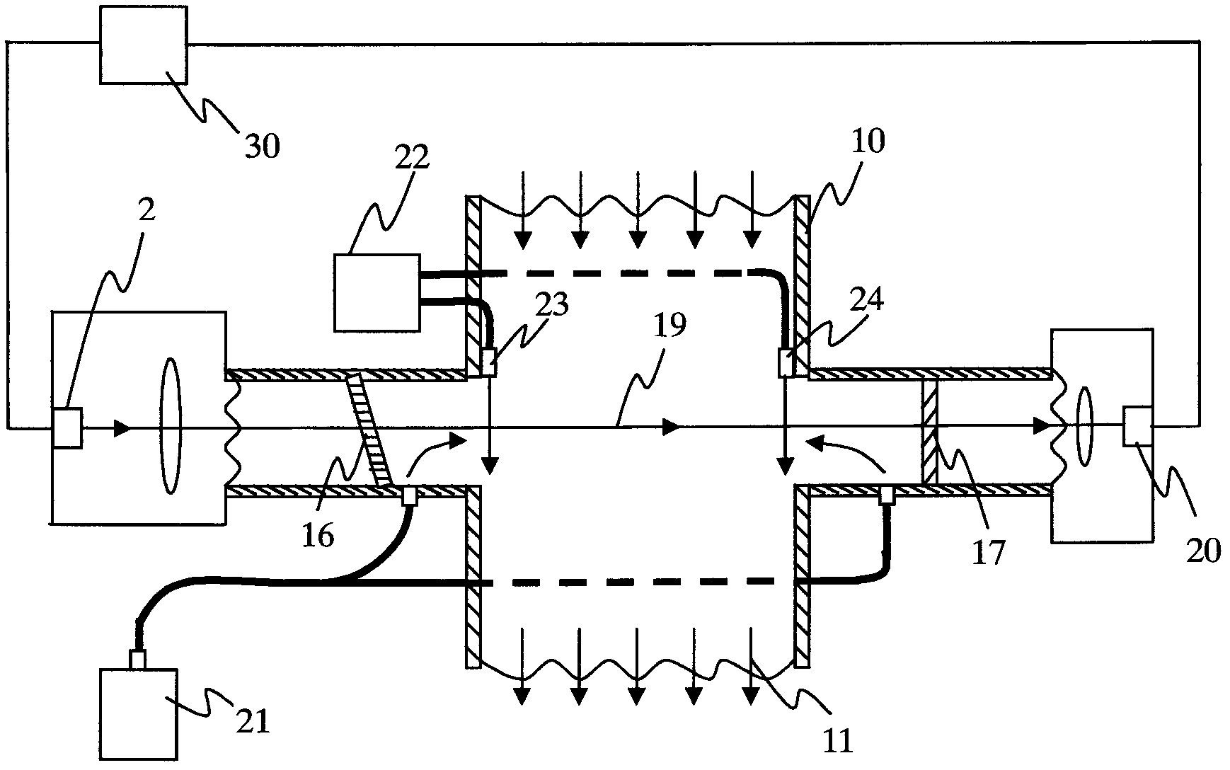
[0057] image 3 The basic structure diagram of the on-site gas measuring device according to the embodiment of the present invention is schematically given. Such as image 3 As shown, the difference between the gas measuring device and Embodiment 1 is:

[0058] The measuring device further includes an inner tube for passing the measuring beam 19 and the first gas, and the gas interfaces 23, 24 are arranged at the end of the inner tube deep into the pipeline. Optionally, the gas channel is arranged outside the inner tube.

Example Embodiment

[0059] Example 3:

[0060] An application example of the measuring device and method according to Embodiment 2 of the present invention in the detection of hydrogen sulfide in a natural gas pipeline.

[0061] In this application example, the light source is a VCSEL laser, and the emitted wavelength contains the absorption spectrum line 1588nm corresponding to hydrogen sulfide, the flow rate of the first gas is 2m / s, and the flow rate of the process gas in the pipeline is 0.1m / s , The width of the gas interface is 0.2mm, and the flow rate of the second gas passing through the gas interface is 120m / s. At this time, the second gas forms a gas wall that separates the first gas from the process gas, such as Figure 4 As shown, there is a measurement optical path between the two gas walls, which ensures the stability of the measurement optical path, thereby reducing measurement errors.


PUM


Abstract

The invention discloses an in-place gas measurement method, which comprises the following steps: a, a first gas is lead towards one side of a process gas in a pipe which is adjacent to an optical window between a light source and a detector, a gas port is arranged at the position of a pipe where the first gap enters, and a second gas is lead in at the position of the gas port so that the second gas enters the pipe along the flow direction of the process gas in the pipe to form a gas wall which cuts off the first gas and the process gas and stability of a measuring optical path is maintained; b, measuring lights sent out by the light source pass through the optical window, the first gas, the second gas and the process gas in the pipe, and received by the detector, and the output signals of the detector are transmitted to an analytical unit; c, the analytical unit processes the signals transmitted by the detector by means of spectrum technology so that concentration of a gas to be measured in the process gas. An in-place gas measurement device is further disclosed. The in-place gas measurement method and the in-place gas measurement device have the advantages of being stable in the measuring light path, small in measurement error, and widely applicable to technical fields such as metallurgy, chemical industry, cement, environmental protection and the like.

Description

technical field [0001] The invention relates to gas analysis, in particular to an on-site gas measurement method and device. Background technique [0002] In the fields of metallurgy, chemical industry, cement, power generation, etc., on-site gas measuring devices are widely used to analyze parameters such as gas concentration in process pipelines. The measured gas parameters are helpful for optimizing production processes, improving production efficiency, saving energy and reducing pollution. emissions etc. are important. [0003] figure 1 Schematically gives the basic structure diagram of the commonly used in-situ gas measurement device in the prior art, such as figure 1 As shown, the light emitting unit 14 and the light receiving unit 15 are arranged on both sides of the process pipeline 10, and the gas to be measured 11 is isolated by the windows 16 and 17; wherein, the light source 2 is arranged in the light emitting unit 14, and the detector 20 is arranged in the In...

Claims


Application Information

Patent Timeline
IPC IPC(8): G01N21/35G01N21/3504
Inventor 俞大海陈立波张飞马海波
Owner FOCUSED PHOTONICS
Why Eureka
Try Eureka