Device for detecting gas in single-end in-situ pipeline, and working method thereof

A gas detection and pipeline technology, applied in the direction of measuring devices, color/spectral characteristic measurement, material analysis through optical means, etc., can solve problems such as low reliability, abnormal measurement of instruments, complex pretreatment structure, etc., to improve operation The effect of stability and reliability

Active Publication Date: 2018-06-08
FOCUSED PHOTONICS
View PDF11 Cites 2 Cited by
  • Summary
  • Abstract
  • Description
  • Claims
  • Application Information

AI Technical Summary

Problems solved by technology

[0005] 2. The installation has small space requirements, and for some occasions where the installation space is insufficient, only single-ended installation can be performed;
[0009] 1. Since the reflective end is inserted into the pipe, the reflective lens is easily polluted by the process gas. After the pollution causes the reflected light intensity to drop to a critical point, the instrument will not be able to measure normally;
[0010] 2. After the reflective lens is polluted, it is difficult to maintain due to the gas inside the pipe
[0011] For the above-mentioned in-situ gas analysis instrument with purging structure, when the pressure of the gas in the pipeline is relatively stable, ...

Method used


Image

  • Device for detecting gas in single-end in-situ pipeline, and working method thereof

Examples


Embodiment 1

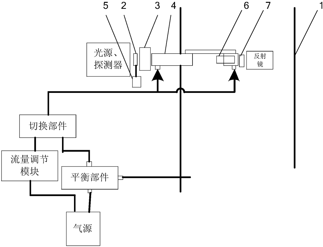
[0049] figure 1 A schematic diagram of the structure of the single-end in-situ gas detection device in the pipeline according to the embodiment of the present invention is schematically given, as shown in figure 1 As shown, the single-end in-situ pipeline gas detection device includes:

[0050]A light source, a detector, and a first tube 4 extending into the pipeline 1, the part of the first tube 4 protruding into the pipeline 1 has a gap facing away from the airflow direction in the pipeline; the first tube has The part of the notch is arc-shaped or V-shaped or [-shaped in section along the airflow direction in the pipeline;

[0051] The first isolation part 2, such as a glass slide, is arranged on the light path of the measurement light emitted by the light source to pass through the measurement light, and isolates the light source and the gas in the pipeline; along the In the direction of the measuring light, one or both sides of the first isolation member have elastic se...

Embodiment 2

[0075] An application example of the single-end in-situ pipeline gas detection device and its working method in the detection of gas concentration in pipelines according to Embodiment 1 of the present invention.

[0076] In this application example, the in-situ pipeline gas detection device includes:

[0077] A light source, such as a tunable semiconductor laser, the measurement light emitted by the light source passes through the purge unit on one side of the pipeline and then enters the pipeline, interacts with the gas in the pipeline and then passes through the purge unit on the other side of the pipeline After being received by the detector;

[0078] a detector, the detector converts the received optical signal into an electrical signal; the light source and the detector are arranged on opposite sides of the pipeline;

[0079] An analysis unit, the analysis unit uses absorption spectroscopy to process the electrical signal, so as to know the gas content in the pipeline; ...


PUM


Abstract

The invention provides a device for detecting a gas in a single-end in-situ pipeline, and a working method thereof. The gas detection device comprises a light source, a detector, a purging unit and afirst tube extending into the pipeline, and the part, extending into the pipeline, of the first tube has a gap facing away from the direction of gas flow in the pipeline. The device for detecting thegas in the single-end in-situ pipeline further includes: a first isolation part arranged on the light path of measurement lights emitted by the light source to make the measurement lights penetrate and used for isolating the light source from the gas in the pipeline, wherein one side or two sides of the first isolation part is/are provided with one or two elastic sealing parts along the directionof the measurement lights; and a driving unit for transmitting energy to the first isolation part to make the first isolation part vibrate back and forth along the direction of the light path of the measurement lights. The device has the advantages of high detection precision and the like.

Description

technical field [0001] The invention relates to gas detection, in particular to a single-end in-situ gas detection device in a pipeline and a working method thereof. Background technique [0002] For gas analysis instruments for in-situ measurement, in order to protect the optical system of the analysis instrument from being polluted by dust and oil in the process gas, clean high-pressure nitrogen or instrument-grade compressed air is usually used for purging protection. [0003] Single-ended in-situ laser gas analyzers have the following advantages over pierced laser analyzers: [0004] 1. Easy to install, only need to open a hole for installation, only need to build a single-sided platform, only need to put a single-sided cable, only need one side of the valve and other materials, reducing engineering installation costs; [0005] 2. The installation has small space requirements, and for some occasions where the installation space is insufficient, only single-ended install...

Claims


Application Information

Patent Timeline
IPC IPC(8): G01N21/15G01N21/39
CPCG01N21/15G01N21/39G01N2021/155G01N2021/151G01N2021/391Y02A50/20
Inventor 刘卫卫俞大海
Owner FOCUSED PHOTONICS
Why Eureka
Try Eureka