In-situ in-pipe gas detection device and working method thereof

A gas detection and pipeline technology, which is applied in the direction of measuring devices, color/spectral characteristic measurement, material analysis through optical means, etc., can solve the problems of not being able to find, not truly reflecting the true concentration of gas in the pipeline, and low reliability

Active Publication Date: 2018-07-27
FOCUSED PHOTONICS
View PDF6 Cites 0 Cited by
  • Summary
  • Abstract
  • Description
  • Claims
  • Application Information

AI Technical Summary

Problems solved by technology

[0003] For the above-mentioned in-situ gas analysis instrument with purging structure, when the pressure of the gas in the pipeline is relatively stable, the analysis instrument can accurately reflect the true concentration of the gas in the pipeline; when the pressure of the gas in the pipeline fluctuates, the output of the analysis instrument The gas concentration value fluctuates accordingly, which can no longer truly

Method used


Image

  • In-situ in-pipe gas detection device and working method thereof

Examples


Embodiment 1

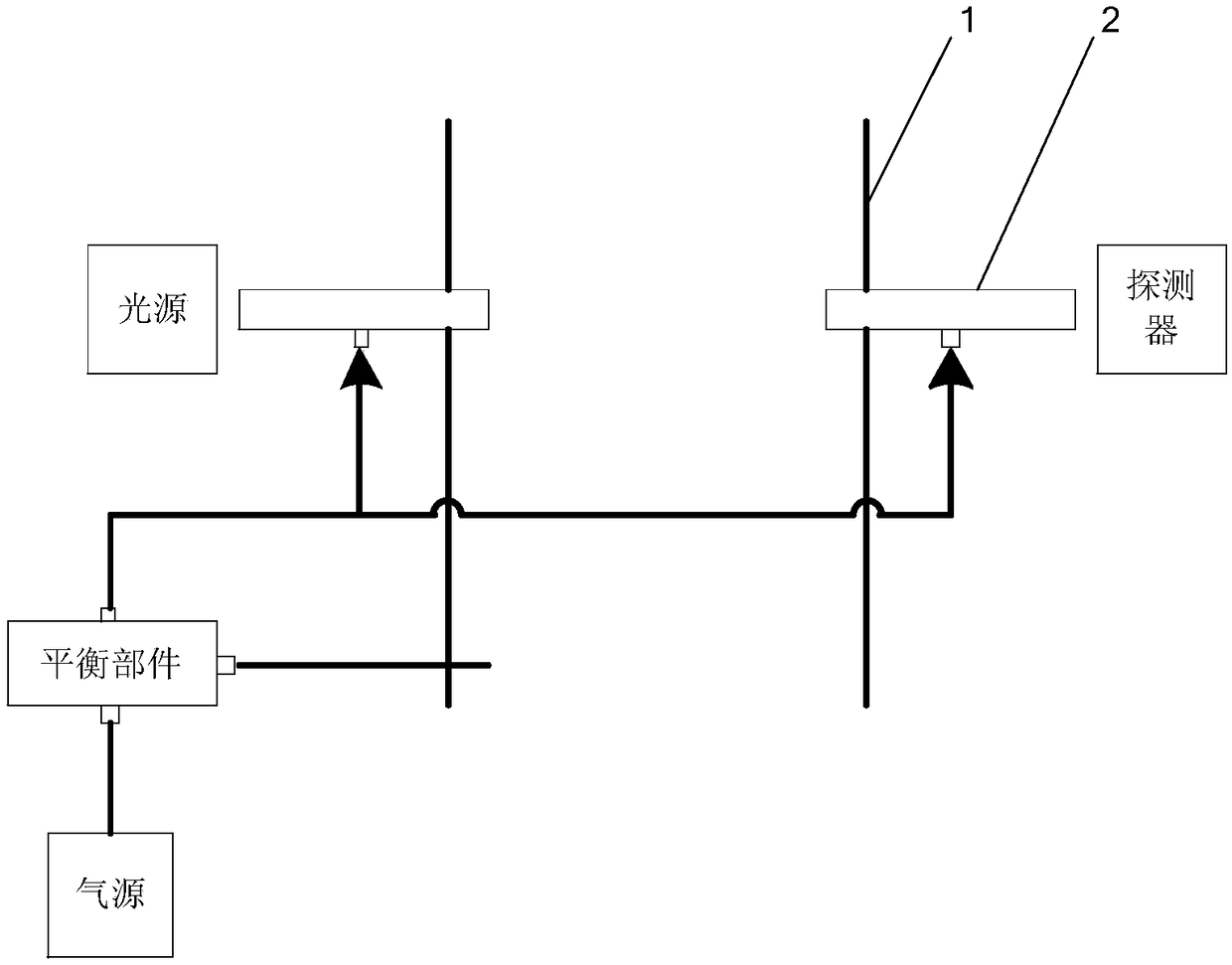
[0039] figure 1 A schematic structural diagram of the in-situ gas detection device in the pipeline according to the embodiment of the present invention is schematically given, as shown in figure 1 As shown, the in-situ pipeline gas detection device includes:

[0040] A purge unit, the purge unit is connected to the interior of the pipeline, and the purge gas enters the purge unit, thereby isolating the optical device and the gas in the pipeline to prevent the optical device from being polluted;

[0041] A balancing component, the balancing component comprising:

[0042] a cylindrical member, one end of the cylindrical member communicates with the interior of the pipeline through a pipeline;

[0043] a piston disposed within the barrel;

[0044] a spring, one end of the spring is fixed on the piston, and the other end is fixed on the cylindrical member;

[0045] A gas inlet and a gas outlet, the gas inlet and the gas outlet are arranged on opposite sides of the cylinder, th...

Embodiment 2

[0051] An application example of the in-situ pipeline gas detection device and its working method according to Embodiment 1 of the present invention in the detection of gas concentration in pipelines.

[0052] In this application example, the in-situ pipeline gas detection device includes:

[0053] A light source, such as a tunable semiconductor laser, the measurement light emitted by the light source passes through the purge unit on one side of the pipeline and then enters the pipeline, interacts with the gas in the pipeline and then passes through the purge unit on the other side of the pipeline After being received by the detector;

[0054] a detector, the detector converts the received optical signal into an electrical signal; the light source and the detector are arranged on opposite sides of the pipeline;

[0055] An analysis unit, the analysis unit uses absorption spectroscopy to process the electrical signal, so as to know the gas content in the pipeline;

[0056] In...


PUM


Abstract

The invention provides an in-situ in-pipe gas detection device and a working method thereof. The in-situ in-pipe gas detection device comprises a purging unit communicating with the interior of a pipeand further comprises a balancing component, wherein the balancing component comprises a tubular member, a piston, a spring, a gas inlet and a gas outlet; one end of the tubular member communicates with the interior of the pipe through a pipeline; the piston is arranged in the cylindrical member; one end of the spring is fixed on the piston, and the other end of the spring is fixed on the tubularmember; the gas inlet and the gas outlet are form in two opposite sides of the tubular member; and the gas outlet communicates with the purging unit. The ratio M of an overlapping area S1 between theside surface of the piston and the gas outlet to the sectional area S2 of the gas outlet belongs to the set [0, 1]; i.e., the relation of the change delta<S1> of the overlapping area S1 and the deformation quantity delta<x> of the spring satisfies the equation that delta<S1>=k*delta<x>, wherein k is a constant; and k=(K*S2/P<lambda>*S3), wherein P<lambda> is gas pressure at the gas inlet, K is the elasticity coefficient of the spring, and S3 is the sectional area, perpendicular to the direction of movement, of the piston. The in-situ in-pipe gas detection device of the invention has the advantages of high detection precision and the like.

Description

technical field [0001] The invention relates to gas detection, in particular to an in-situ gas detection device in a pipeline and a working method thereof. Background technique [0002] For gas analysis instruments for in-situ measurement, in order to protect the optical system of the analysis instrument from being polluted by dust and oil in the process gas, clean high-pressure nitrogen or instrument-grade compressed air is usually used for purging protection. [0003] For the above-mentioned in-situ gas analysis instrument with purging structure, when the pressure of the gas in the pipeline is relatively stable, the analysis instrument can accurately reflect the true concentration of the gas in the pipeline; when the pressure of the gas in the pipeline fluctuates, the output of the analysis instrument The gas concentration value fluctuates accordingly, which cannot truly reflect the true concentration of the gas in the pipeline. [0004] The above-mentioned problems have ...

Claims


Application Information

Patent Timeline
IPC IPC(8): G01N21/15G01N21/39
CPCG01N21/15G01N21/39G01N2021/151
Inventor 俞大海
Owner FOCUSED PHOTONICS
Why Eureka
Try Eureka