Equipment and method for optical analysis of fluids
An optical analysis and fluid technology, applied in the field of fluid analysis, can solve problems such as complex structure, high cost, poor stability, etc., and achieve the effects of high measurement accuracy, accurate fluid analysis, and stable measurement optical path
- Summary
- Abstract
- Description
- Claims
- Application Information
AI Technical Summary
Problems solved by technology
Method used
Image

Examples
Embodiment 1
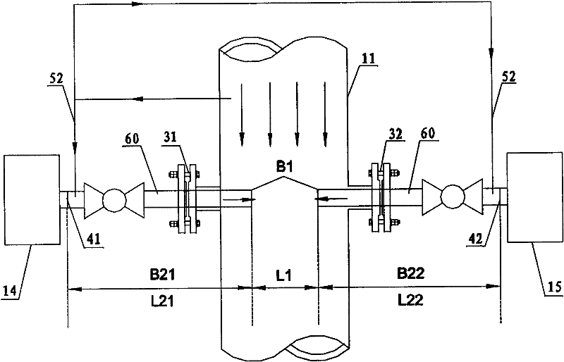
[0071] figure 2 A basic structure diagram of the optical analysis device for fluid according to the embodiment of the present invention is schematically given. like figure 2 As shown, the optical analysis equipment includes:
[0072] The light source, which is used to emit measurement light, is arranged in the light receiving unit 14; the light source can be a laser, a xenon lamp, or the like.
[0073] A detector, such as a photoelectric sensor, is arranged in the light receiving unit 15, and the detector is used to combine the received measurement light with the fluid (gas) in the first measurement area B1 and the second measurement area (including B21 and B22). or liquid) after the action of the optical signal is converted into an electrical signal, and transmitted to the analysis unit (not shown). The light sources and detectors are installed on one side or both sides of the pipeline 11 through mechanical connection structures (such as flanges 31, 32). The fluid (gas ...
Embodiment 2
[0088] According to the application example of the optical analysis equipment and method in Embodiment 1 of the present invention in the iron and steel industry, it is specifically applied to the analysis of the O2 content in the gas in front of the gas cabinet.
[0089] Figure 4 The basic structural diagram of the optical analysis device is schematically given. like Figure 4 As shown, the optical analysis equipment includes:
[0090] The light source in the analysis device adopts a laser, which is arranged in the light emitting unit 14, and the wavelength of the measurement light emitted by the laser includes the wavelength corresponding to the absorption spectrum line of O2, such as 763nm.
[0091] The detector adopts a photoelectric sensor, which is arranged in the light receiving unit 15, and the detector is used to pass the measurement light through the first measurement area B1 (the optical path is L1) and the second measurement area (including B21 and B22, The opti...
Embodiment 3
[0101] According to the application example of the optical analysis equipment in embodiment 1 of the present invention in the iron and steel industry, it is specifically applied in the analysis of the calorific value of gas in front of the heating furnace of the steel rolling mill. The calorific value of the converter gas is calculated by measuring the content of CO in the converter gas on-line (that is, on-site), and provides calorific value data for the control of the combustion air-fuel ratio of the heating furnace.
[0102] Figure 5 The basic structural diagram of the optical analysis device is schematically given. like Figure 5 As shown, the optical analysis equipment includes:
[0103] The light source is a laser, which is arranged in the light emitting unit 14, and the wavelength of the measurement light emitted by the laser includes the wavelength corresponding to the absorption spectrum line of CO, such as 1583nm.
[0104] The detector adopts a photoelectric sens...
PUM
 Abstract
Description
Claims
Application Information
 - Generate Ideas
- Intellectual Property
- Life Sciences
- Materials
- Tech Scout
- Unparalleled Data Quality
- Higher Quality Content
- 60% Fewer Hallucinations
Browse by: Latest US Patents, China's latest patents, Technical Efficacy Thesaurus, Application Domain, Technology Topic, Popular Technical Reports.
© 2025 PatSnap. All rights reserved.Legal|Privacy policy|Modern Slavery Act Transparency Statement|Sitemap|About US| Contact US: help@patsnap.com