Optical sensor and detection method thereof
An optical sensor, sensor technology, applied in the direction of material excitation analysis, etc., can solve the problems of high complexity of stay and detection, and achieve the effect of prolonging the service life, safe operation mode and compact structure
- Summary
- Abstract
- Description
- Claims
- Application Information
AI Technical Summary
Problems solved by technology
Method used
Image
Examples
specific Embodiment
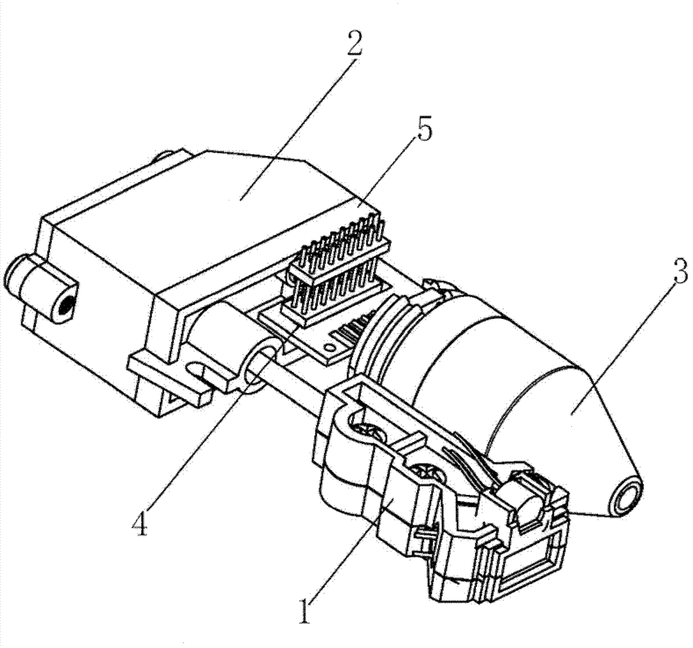
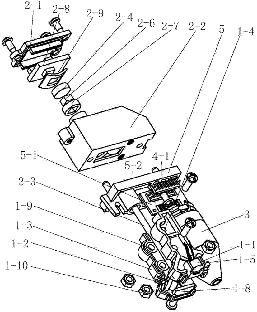
[0042] refer to figure 1 and figure 2 , the present embodiment includes a transmitting module 1, a receiving module 2, an infrared shooting sensor module 3 and a signal transfer transmission module 4;
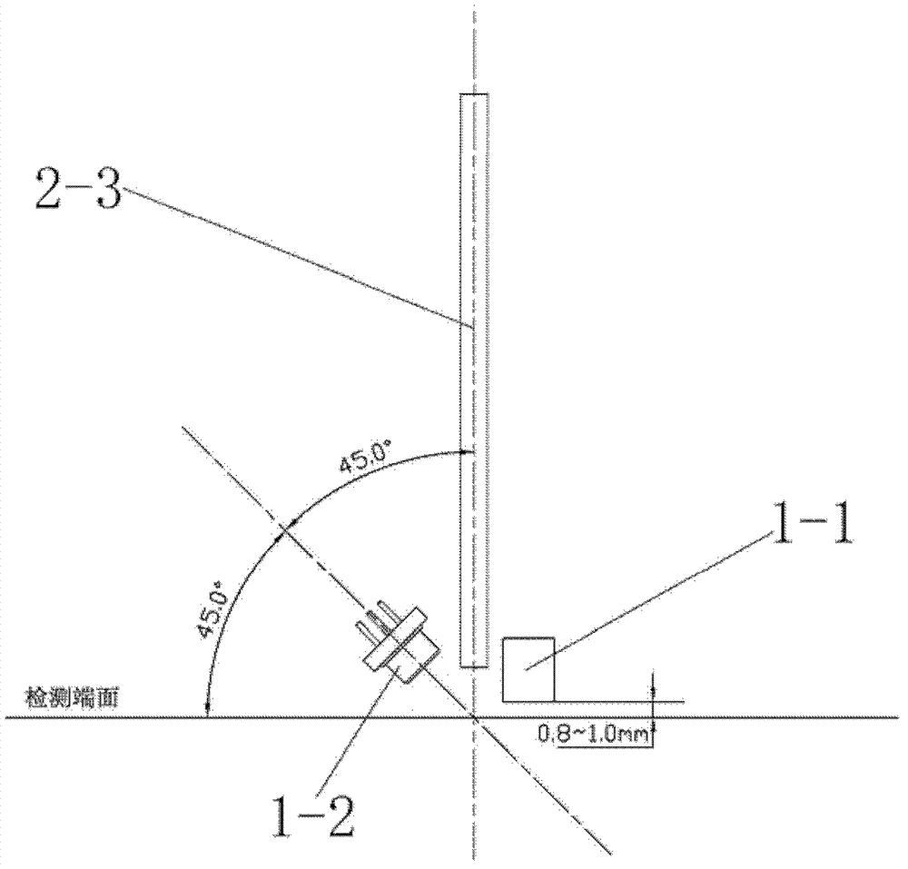
[0043] 1) The emission module 1 has an automatic detection control sensor 1-1 and a semiconductor laser 1-2; after the automatic detection control sensor 1-1 detects that the optical sensor is close to the substrate, the automatic detection control sensor 1-1 sends a detection control signal to the semiconductor laser At the input end of the laser 1-2, the semiconductor laser 1-2 emits a detection beam to scan the surface of the substrate after receiving the detection control signal; when the surface of the substrate contains a normal-shaped or regular anti-counterfeiting feature signal area, the detection beam The scanned place will excite a response beam;
[0044] 2) The receiving module 2 has a light guiding device, a light filtering device, a photoelectric sensor and a s...
specific Embodiment 2
[0063] The optical sensor of this embodiment is characterized in that: the control signal input terminal of the infrared shooting sensor module 3 is also connected to the control signal output terminal of the transmitting module 1, and other structures are the same as the optical sensor of the specific embodiment 1.
[0064] The detection method of the optical sensor of the present embodiment is characterized in that: in step 4), the infrared shooting sensor module 3 starts: when the automatic detection control sensor of the emission module 1 in step 2) detects the detection end face of the optical sensor When it is close to the surface of the substrate, the emission module 1 sends a shooting instruction to the infrared shooting sensor module 3, and the infrared shooting sensor module 3 receives the shooting instruction, starts shooting, and outputs the captured image information to the signal transfer transmission module 4; Infrared shooting sensor module 3 can start working a...
specific Embodiment 3
[0065] The feature of the optical sensor in this embodiment is: the control signal input terminal of the infrared shooting sensor module 3 is also connected to the control signal output terminal of the central processing unit. Other structures are the same as those of the optical sensor in Embodiment 1.
[0066] The detection method of the optical sensor of the present embodiment is characterized in that: in step 4), the infrared shooting sensor module 3 starts: when the signal preprocessing circuit of the receiving module 2 in step 3) outputs the digital signal to the signal transfer transmission After the module 4, the signal transfer transmission module 4 transmits the digital signal to the central processing unit. After the central processing unit judges and processes the signal, if it considers the signal to be a valid signal, it sends a shooting instruction to the infrared shooting sensor module 3. , the infrared shooting sensor module 3 receives the shooting instruction...
PUM
 Abstract
Description
Claims
Application Information
 - R&D
- Intellectual Property
- Life Sciences
- Materials
- Tech Scout
- Unparalleled Data Quality
- Higher Quality Content
- 60% Fewer Hallucinations
Browse by: Latest US Patents, China's latest patents, Technical Efficacy Thesaurus, Application Domain, Technology Topic, Popular Technical Reports.
© 2025 PatSnap. All rights reserved.Legal|Privacy policy|Modern Slavery Act Transparency Statement|Sitemap|About US| Contact US: help@patsnap.com


