Cable clamp for one-time current rise of closed switch cabinet

A switchgear and test technology, applied in switchgear, electrical components, etc., can solve the problems of small internal space of 10kV closed switchgear, inconvenient use of closed switchgear, low work efficiency, etc. Convenient, compact effect

Inactive Publication Date: 2012-07-11
QINGZHOU POWER SUPPLY
View PDF4 Cites 7 Cited by
  • Summary
  • Abstract
  • Description
  • Claims
  • Application Information

AI Technical Summary

Problems solved by technology

[0004] However, it was found in the work that the internal space of the 10kV closed switchgear is small, and the CT mostly uses the ZZBJ9 type, and the crimping screws are mostly 12mm in diameter, and a few are 10mm. To meet safety requirements, the primary leads on both sides of the CT are usually covered with insulating sheaths, and only the copper bars and screws close to the CT surface are exposed, while the traditional test wire clamp has a relatively large and tight structure to ensure the flow capacity of the contact surface. It is very difficult for one person to operate with one hand, and it is not convenient to use in a closed switch cabinet
[0005]In addition, during the test, only the copper bar screw connecting the CT and the static contact of the switch can only be loosened temporarily, and the connection nose of the output line of the large current generator and the CT should be drawn out at one time After the end is pressed, the test is carried out, and the test is resumed after the end. The process is cumbersome, resulting in a long time-consuming and low work efficiency when doing a current-raising test in a 10kV closed switch cabinet.

Method used


Image

  • Cable clamp for one-time current rise of closed switch cabinet
  • Cable clamp for one-time current rise of closed switch cabinet
  • Cable clamp for one-time current rise of closed switch cabinet

Examples


Embodiment

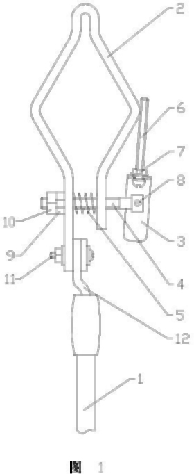
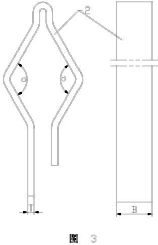
[0040] Example: such as figure 1 As shown in the figure, the wire clamp for the one-time up-current test of the closed switch cabinet includes a handle 1, and the handle 1 is provided with a current wire nose 12, and the current wire nose 12 is fixedly connected with a fastening wire clip 2 through a fixing bolt 11, and the fastening wire The clip 2 is in the shape of a rhombus, one set of diagonal angles of the rhombus is 120°, and the diagonal angles of 120° are located on both sides of the extension line of the current wire lug 12 .

[0041] When the diamond-shaped fastening clamp 2 is connected to the CT in the airtight switch cabinet, since the joint is a hexagonal nut, and the included angle of the hexagonal nut is 120°, the four sides of the fastening clamp 2 can be in contact with the hexagonal nut. The contact area is large and the fastening is reliable.

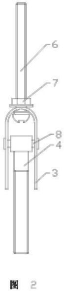
[0042] The opening side of the fastening clamp 2 is provided with a pressing device, and the pressing device in...


PUM


Abstract

The invention discloses a cable clamp for one-time current rise of a closed switch cabinet. The cable clamp comprises a handle, wherein a current line nose is arranged on the handle, and the current line nose is fixedly connected with a fastening cable clamp. The cable clamp is characterized in that the fastening cable clamp is rhombic. Due to the adoption of the technical scheme, the cable clamp provided by the invention has the characteristics of strong pertinence, convenience in operation, firmness in connection, safety, reliability, strong applicability and the like.

Description

technical field [0001] The invention relates to an electric device, in particular to a wire clip for a test of a closed switch cabinet for a current uplift. Background technique [0002] An upflow test is an indispensable work for the daily protection transmission test. Especially when replacing the CT and verifying the work of the protection device, it is often judged whether there is any error in the secondary wiring of the equipment and whether the protection setting is accurate through a current test. Its workflow is as follows: [0003] Start→Remove the rear cabinet door→Fix the high current generator current clamps at both ends of the CT→Start the high current generator loading current test→Remove the current clamps→Install the rear cabinet door→End. [0004] However, it was found in the work that the internal space of the 10kV closed switchgear is small, and the CT mostly uses the ZZBJ9 type, and its crimping screws are mostly 12mm in diameter, and a few are 10mm. ...

Claims


Application Information

Patent Timeline
Patent Type & Authority Applications(China)
IPC IPC(8): H02B3/00
Inventor 张跃勇曾刚崔超刘帅翟安冯涛陈其涛周轮刘全
Owner QINGZHOU POWER SUPPLY
Why Eureka
Try Eureka