Smart safeguard fence

An intelligent security and fence technology, applied in the direction of fence, energy-saving ICT, anti-theft alarm mechanical activation, etc., can solve the problems of wasting power resources, line damage, high false alarm rate, etc., to save energy costs, not easy to be destroyed, safety high effect

Inactive Publication Date: 2013-05-01
JIANGNAN UNIV
View PDF4 Cites 47 Cited by
  • Summary
  • Abstract
  • Description
  • Claims
  • Application Information

AI Technical Summary

Problems solved by technology

[0004] a. Only through the principle of infrared and laser beams, the alarm is greatly disturbed by the external environment, rain and fog weather is prone to false alarms, and the interference caused by some wild animals cannot be well eliminated, and there is a high false alarm rate
[0005] b. The video surveillance equipment needs to be turned on all the time to achieve real-time monitoring. If the surveillance personnel also monitor the real-time data captured by the camera in real time, a lot of human resources will be wasted, and the always-on camera will waste power resources
[0006] c. It is a good method to have high-voltage pulses to achieve active repulsion, but if the fence is always connected to high-voltage pulses, the safety of the equipment will be challenged, and a lot of power resources will inevitably be wasted
[0007] d. The controller of the fence needs to send the data through the data cable: on the one hand, the distance between the fence and the control room is far away, and it is inconvenient to set up the line; on the other hand, the line may be artificially damaged
[0008] Therefore, the existing security fences have relatively large limitations in perimeter protection applications.

Method used


Image

  • Smart safeguard fence
  • Smart safeguard fence
  • Smart safeguard fence

Examples


Embodiment Construction

[0023] The present invention will be described in detail below in conjunction with the accompanying drawings and specific embodiments.

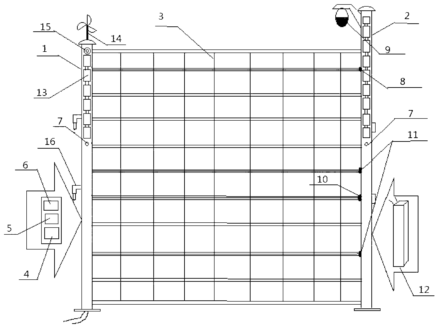
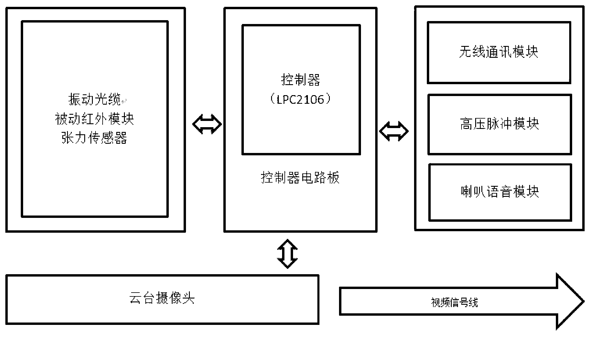
[0024] Such as figure 1 As shown, the intelligent security fence designed by the present invention includes: a first pole 1, a second pole 2, a fence 3, a coupler 16, a controller 5, a wireless communication module 6, a sensor group, a power supply system, and a high-voltage pulse module 8 , PTZ camera 9, speaker voice module 15. The invention adopts a built-in integrated mechanical structure, adopts multiple sensors for signal collection and processing, and uses wind energy, light energy, and power grid for complementary power supply.

[0025] The sensor group includes: a passive infrared module 7 , a vibration optical cable 10 , and a tension sensor 11 .

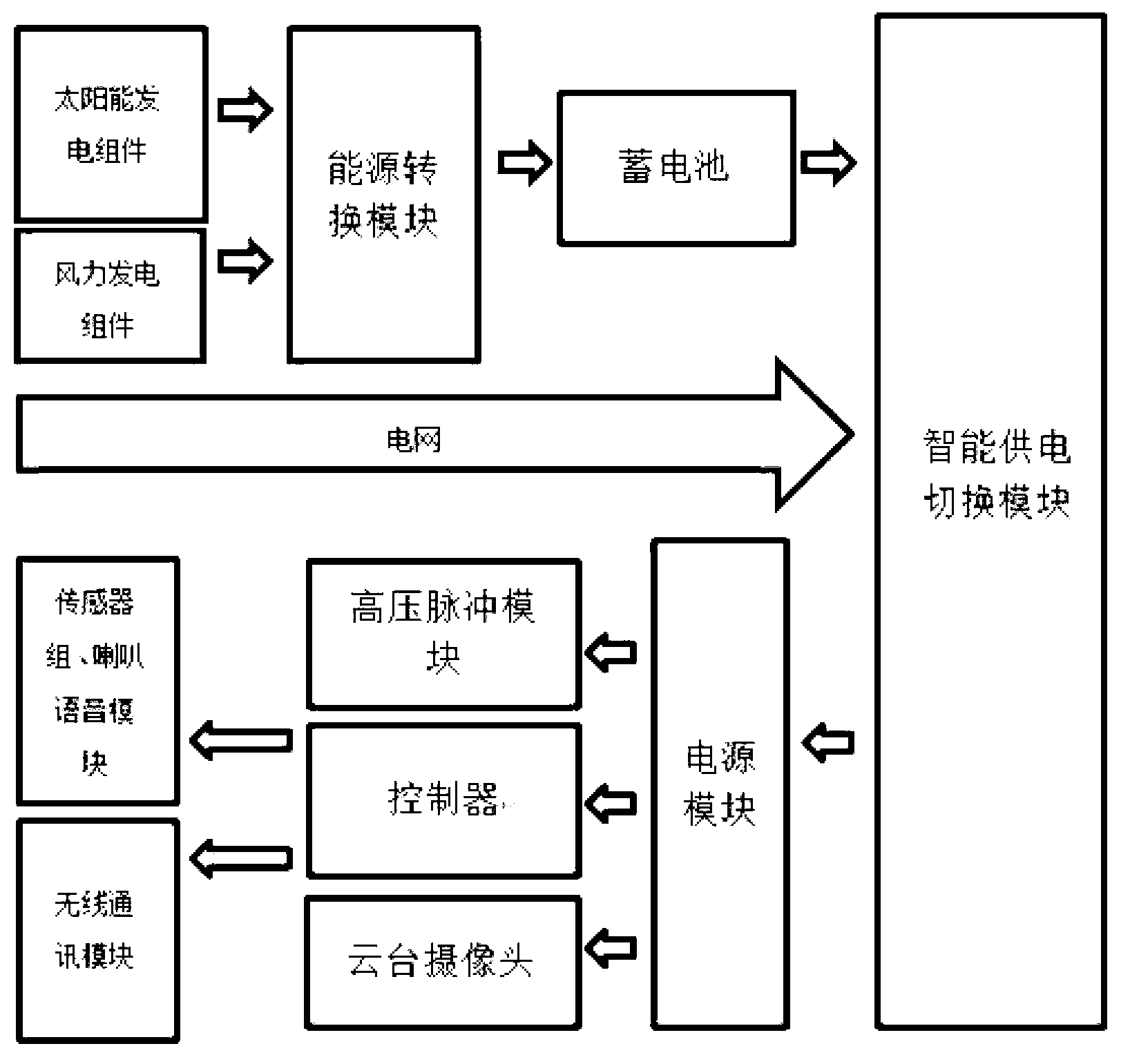
[0026] The power supply system includes: a solar photovoltaic power generation component 13 , a wind power generation component 14 , a power module 4 , and a storage battery 12 . The p...


PUM


Abstract

The invention discloses a smart safeguard fence, comprising a left upright post, a right upright post and a net fence between the left and right upright posts, wherein a vibration optical cable is arranged in the fence, two ends of the vibration optical cable are respectively connected with a tension sensor and a high voltage pulse module which are arranged in the upright posts, a passive infrared module, a wireless communication module, a microcontroller, a power source module and a storage cell are mounted further in the upright posts, the power source module comprises an energy conversion module, a smart power supplying switching module and a voltage varying and stabilizing module, cloud deck cameras are mounted at the tops of the upright posts, solar generating assemblies are paved at the outer faces of the upper parts of the upright posts, and the microcontroller is communicated with a monitoring center by the wireless communication module. Couplers are respectively arranged at the two upright posts, and a whole safeguard fence system is formed by connecting and inserting the couplers among multiple safeguard fences. The smart safeguard fence has the advantages of high alarming accuracy rate, strong video monitoring pertinence, good safe performance, energy and power saving, and the like.

Description

technical field [0001] The invention relates to an electronic protection monitoring and alarm device, in particular to an intelligent security fence. Background technique [0002] At present, the fences used for security are generally made of simple masonry concrete, steel wire fences, or plastic wood, etc., lacking intelligent alarms, intelligent monitoring devices such as video infrared and active repelling equipment such as high-voltage pulses. Although some fences also have a certain intelligent detection function, the function is single and it is easy to misjudge. [0003] Some existing security fences usually realize detection and alarm by adding infrared and laser radiation equipment; by installing cameras to observe images of designated areas for video surveillance; by connecting high-voltage pulses to achieve active repulsion. However, these methods also have the following disadvantages: [0004] a. Alarming only through the principle of infrared and laser beams i...

Claims


Application Information

Patent Timeline
Patent Type & Authority Applications(China)
IPC IPC(8): E04H17/14G08B13/12
CPCY02B60/50
Inventor 吴定会张磊李想曹京航王旭彤刘承焕周刚耿超
Owner JIANGNAN UNIV
Why Eureka
Try Eureka