Production method of insulation intermediate connector

A technology for insulating joints and production methods, applied in cable joints and other directions, can solve problems such as affecting the normal operation of single-core cables

Inactive Publication Date: 2012-07-11
CHINA KINWA HIGH TECH
View PDF6 Cites 8 Cited by
  • Summary
  • Abstract
  • Description
  • Claims
  • Application Information

AI Technical Summary

Problems solved by technology

In the process of cable connection, the existing insulated intermediate joints will fail to meet the situation that the induced voltage at any point on the metal sheath of the cable is within the installation requirements of the cable during the power-on process of the cable; After the insulating intermediate joint is installed, it will still generate induced voltage with its nearby auxiliary cables, etc., thus affecting the normal operation of the single-core cable

Method used


Image

  • Production method of insulation intermediate connector
  • Production method of insulation intermediate connector
  • Production method of insulation intermediate connector

Examples


Embodiment Construction

[0027] The invention discloses a production method of an insulating intermediate joint, so as to effectively reduce the induced voltage on the metal sheath of the cable, and at the same time reduce the induced voltage of the single-core cable line to adjacent auxiliary cables and communication cables.

[0028] The technical solutions in the embodiments of the present invention will be clearly and completely described below in conjunction with the accompanying drawings in the embodiments of the present invention. Apparently, the described examples are only some examples of the present invention, not all embodiments. Based on the embodiments of the present invention, all other embodiments obtained by persons of ordinary skill in the art without making creative efforts fall within the protection scope of the present invention.

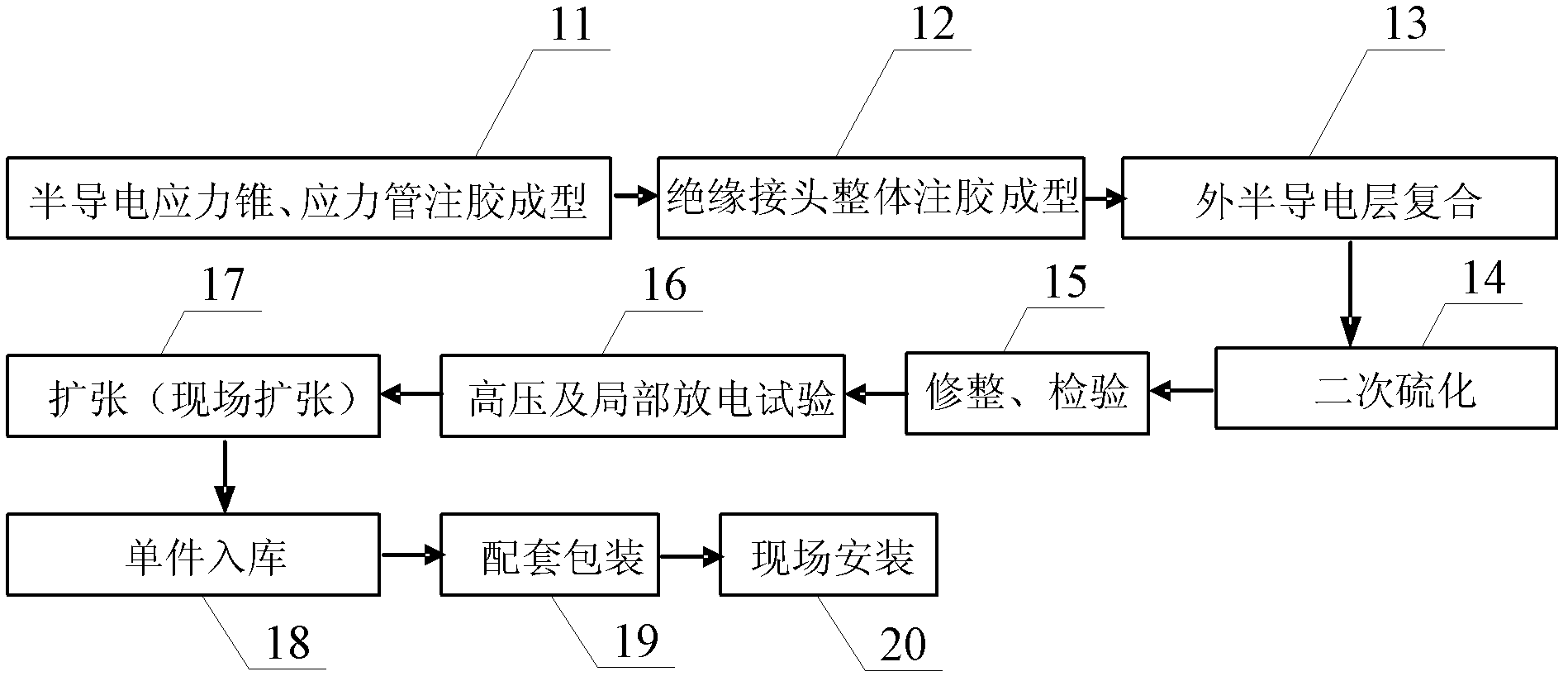
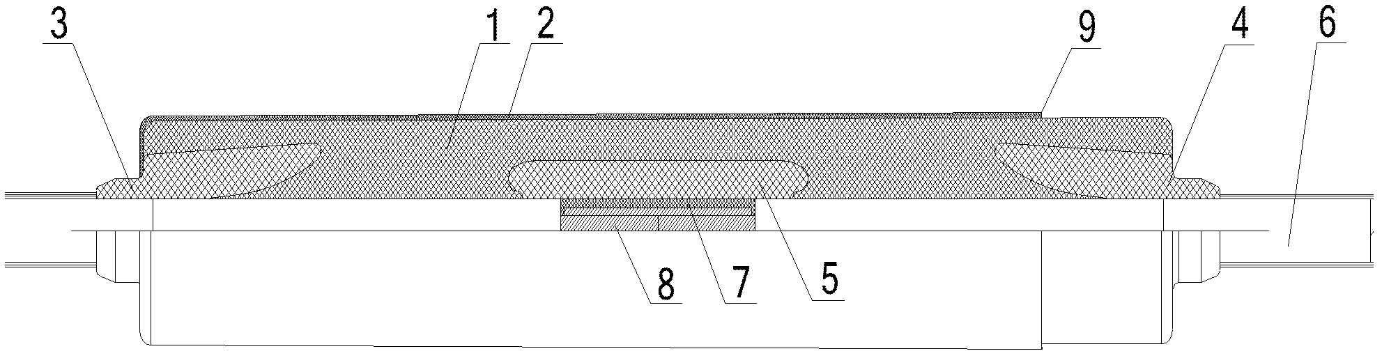
[0029] Such as Figure 1-Figure 2 as shown, figure 1 It is a process flow chart of the production method of the insulating intermediate joint in the pri...


PUM


Abstract

The invention provides a production method of an insulation intermediate connector. The insulation intermediate connector is produced by respectively adopting processes of semiconductive stress cone and stress pipe glue injection molding, insulation connector integral glue injection, external semiconductive layer compounding and secondary vulcanization and expansion, wherein in the semiconductive stress cone and stress pipe glue injection molding process, the mass ratio of a semiconductive liquid silicon rubber component A to a semiconductive liquid silicon rubber component B is 1: (0.8-1.2); and in the insulation connector integral glue injection process, the mass ratio of an insulation liquid silicon rubber component A to an insulation liquid silicon rubber component B is 1: (0.8-1.2). All components in semiconductive liquid silicon rubber and all components in insulation liquid silicon rubber are respectively subjected to glue injection by adopting given mass ratios so as to obtain the insulation intermediate connector. When the insulation intermediate connector is applied to a high-voltage cable, induction voltage on a cable metal sheath can be effectively reduced, and induction voltage of a single-core cable line to auxiliary cables and communication cables can be reduced, wherein the auxiliary cables and the communication cables are adjacent to the single-core cable line.

Description

technical field [0001] The invention relates to the technical field of cable installation, and more specifically relates to a production method of an insulating intermediate joint. Background technique [0002] The core of the 35KV cable and the metal shielding layer surrounding the core are similar to the primary winding structure of a transformer. When the single-core cable core passes current, there will be a magnetic field line crossing the metal shielding layer, so that an induced voltage appears at both ends of the cable. The magnitude of the induced voltage is proportional to the length of the cable line and the current flowing through the cable. When the length of the cable is very long, the induced voltage on the sheath of the outer wall of the cable can be superimposed to a level that endangers personal safety. If there is a short-circuit fault in the cable line during the working process of the cable, or when it is subjected to operating overvoltage or lightning...

Claims


Application Information

Patent Timeline
Patent Type & Authority Applications(China)
IPC IPC(8): H02G15/18B29C35/02
Inventor 李小军徐义全徐明远
Owner CHINA KINWA HIGH TECH
Why Eureka
Try Eureka