
Inductive disturbance reduction device

a technology of inductive disturbance and reduction device, which is applied in the field of inductive disturbance reduction device, can solve the problems of reducing the quality of transmitted ultrasound signal, and achieve the effect of high-quality electrical connection

Inactive Publication Date: 2016-03-10
KONINKLJIJKE PHILIPS NV
View PDF3 Cites 3 Cited by
  • Summary
  • Abstract
  • Description
  • Claims
  • Application Information

AI Technical Summary

Benefits of technology

The patent describes a device that reduces interference in electrical connectors, particularly in cases where high-speed signals need to be transmitted through the connectors. The device uses an inductive reduction system to cancel out interference caused by magnetic fields. The device can be integrated into existing electrical connectors or cables, making it easy to connect electrical devices without the need for a separate coaxial connector. The technical effect of the device is to improve the quality of signals transmitted through the electrical connectors, reducing interference and improving overall performance.

Problems solved by technology

However, an electrical connector is used for electrically connecting the high current ablation wire and the signal wires to the ablation current source and the ultrasound control unit, respectively, wherein within the electrical connector the signal wires are often less shielded from the magnetic field generated by the high ablation current flowing through the high current ablation wire, which may lead to induced voltages in the signal wires that interfere with the ultrasound signals to be transmitted and therefore diminish the quality of the transmitted ultrasound signals.

Method used


Image

  • Inductive disturbance reduction device
  • Inductive disturbance reduction device
  • Inductive disturbance reduction device

Examples


Embodiment Construction

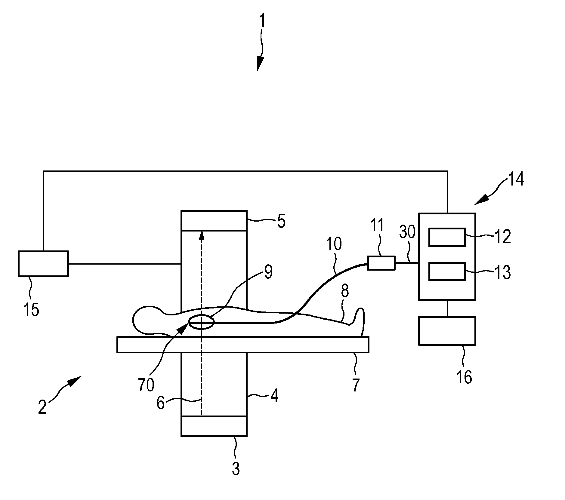
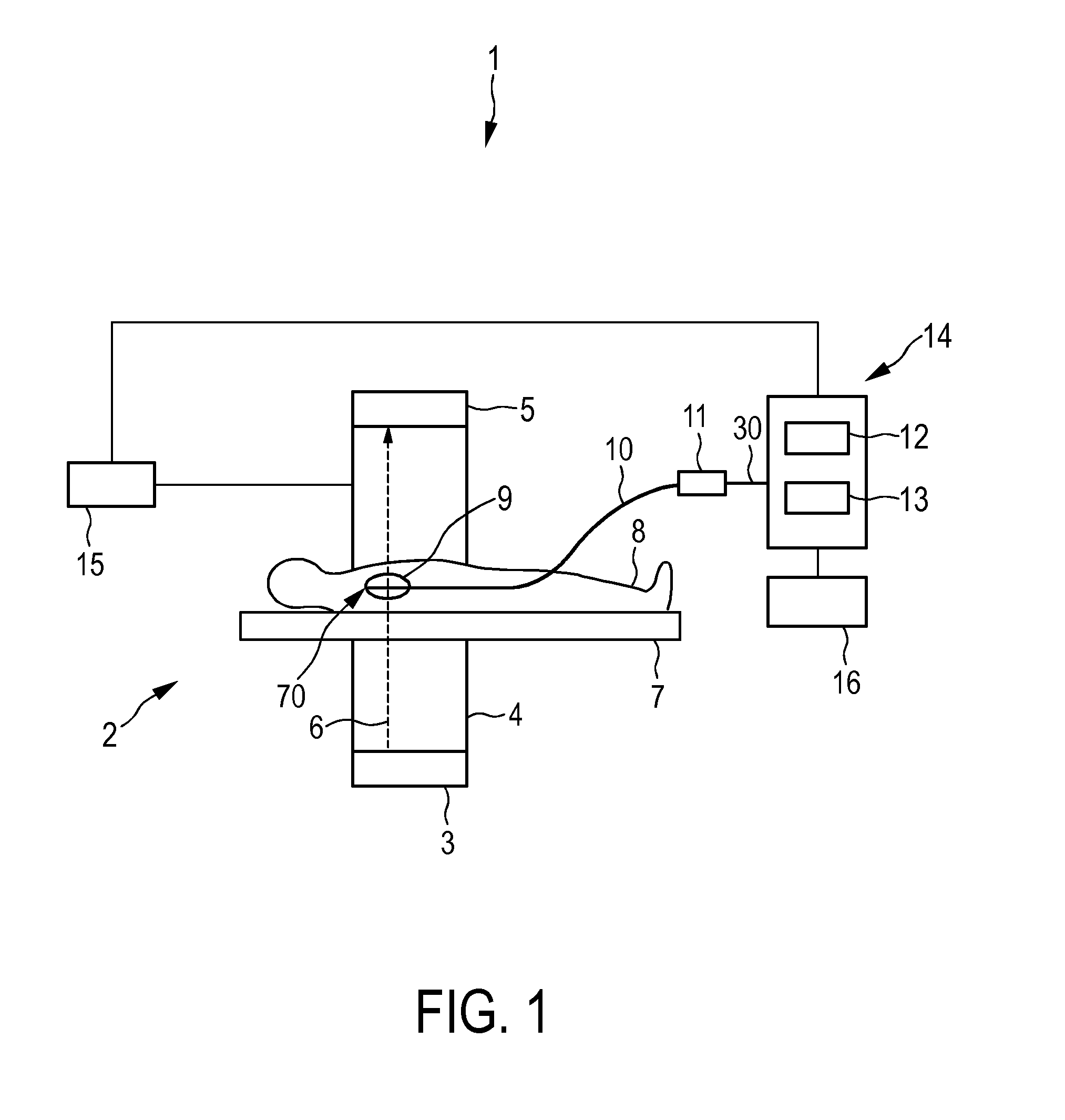
[0039]FIG. 1 shows schematically and exemplarity an embodiment of an ablation system for performing an ablation procedure. The ablation system 1 comprises an ablation catheter 10 for ablating a target region within a person 8 arranged on a support means like a patient table 7. In this embodiment the distal tip of the ablation catheter 10 has been introduced into the heart 9 of the person 8 for ablating cardiac tissue at different locations within the heart 9.

[0040]A fluoroscopy device 2 is used for imaging the distal tip of the ablation catheter 10 within the person 8 during the interventional procedure. The fluoroscopy device 2 comprises an x-ray source 3 for emitting x-rays 6 traversing the person 8 lying on the patient table 7. The fluoroscopy device 2 further comprises an x-ray detector 5 for detecting the x-rays 6, after having traversed the person 8. The x-ray source 3 and the x-ray detector 5 are mounted on a C-arm 4, which is rotatable with respect to the person 8, in order ...


PUM


Abstract

The invention relates to an inductive disturbance reduction device (18) for reducing an inductive disturbance of a signal like an ultrasound signal to be transmitted via first connection conductors (25, 26) of an electrical connector (11), which is caused when ablation current flows through a second connection conductor (24) of the electrical connector. The inductive disturbance reduction device is adapted to induce a voltage, which at least partly compensates a voltage induced in the electrical connector, in order to reduce the inductive disturbance in the signals to be transmitted via the first connection conductors of the electrical connector. Since the inductive disturbance is reduced, a high quality electrical connection can be provided, without necessarily using, for instance, a technically relatively complex and expensive coaxial connector. The inductive disturbance reduction device may be integrated, for instance, in a part of the electrical connector or in a cable.

Description

FIELD OF THE INVENTION[0001]The invention relates to an inductive disturbance reduction device for reducing an inductive disturbance of a signal to be transmitted via first connection conductors of an electrical connector, which is caused when current flows through a second connection conductor of the electrical connector. The invention relates further to an electrical connector comprising the inductive disturbance reduction device and a cable comprising the inductive disturbance reduction device. The invention also relates to a manufacturing apparatus and a manufacturing method for manufacturing the inductive disturbance reduction device.BACKGROUND OF THE INVENTION[0002]In many minimal invasive interventions multipurpose catheters are used, in which treatment and monitoring functionalities are integrated. One example of such a multipurpose catheter is an ablation catheter comprising a radio frequency (RF) ablation tip and sensitive ultrasound elements, i.e. ultrasound transducers, ...

Claims


Application Information

Patent Timeline
IPC IPC(8): A61B18/14
CPCA61B18/1492A61B2018/00178H01R2201/12A61B2090/376A61B2090/3784H01R13/6467A61B2017/00526
Inventor BUDZELAAR, FRANCISCUS PAULUS MARIADELADI, SZABOLCS
Owner KONINKLJIJKE PHILIPS NV
Learn More