Circuit arrangement for switching a current, and method for operating a semiconductor circuit breaker

A circuit device and semiconductor technology, applied in the field of circuit devices, can solve the problems of high switching loss of power semiconductor parts, slow control voltage, etc., and achieve the effect of shortening the on-off duration

Active Publication Date: 2014-04-09
SIEMENS AG
View PDF6 Cites 3 Cited by
  • Summary
  • Abstract
  • Description
  • Claims
  • Application Information

AI Technical Summary

Problems solved by technology

[0008] The disadvantage of this solution is that the control voltage drops only slowly with a ramp-shaped curve for a duration during which the switching losses on the power semiconductors are very high

Method used


Image

  • Circuit arrangement for switching a current, and method for operating a semiconductor circuit breaker
  • Circuit arrangement for switching a current, and method for operating a semiconductor circuit breaker
  • Circuit arrangement for switching a current, and method for operating a semiconductor circuit breaker

Examples


Embodiment Construction

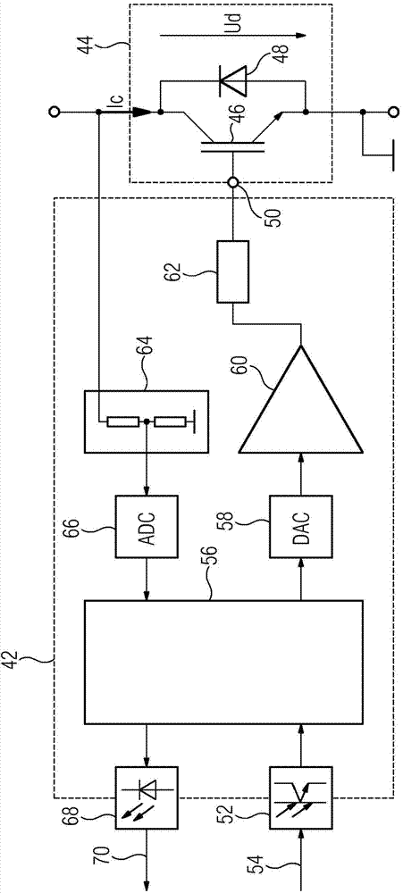
[0036] exist figure 2 Shown in the control circuit 42, the control circuit is mounted on (in figure 2 not shown in detail) in the controllable converter of the frequency converter. The design of the converter can correspond, for example, to that of the converter 10 . The control circuit 42 controls the semiconductor circuit breaker 44 . This semiconductor circuit breaker has a transistor 46 (here an IGBT) and a diode 48 connected in antiparallel thereto. Instead of IGBTs, for example, MOSFETs can also be provided. To control the semiconductor circuit breaker 44 , the control circuit 42 generates a control voltage at the control input 50 of the semiconductor circuit breaker 44 . The control input 50 here corresponds to the gate of the IGBT. The control circuit 42 and the semiconductor circuit breaker 44 together represent an embodiment of the circuit arrangement according to the invention. The current Ic is controlled by means of a semiconductor circuit breaker 44 .

...


PUM


Abstract

When switching a current (Ic) by means of a semiconductor circuit breaker (44), provision can be made for a control voltage to be generated at the control input (50) of the semiconductor circuit breaker (44) by an actuation circuit (42) at switching flanks of a switching signal, said control voltage having a profile which is flattened in relation to the profile of the switching signal. One disadvantage of a solution of this kind is that the switching losses in the power semiconductor (44) are very high for the period during which the control voltage is reduced only slowly with a flattened profile. The object of the present invention is to reduce the switching losses in a semiconductor circuit breaker (44). In the case of the circuit arrangement according to the invention, a value can be predefined for a switching parameter of a control device (56) of the actuation circuit (42), it being possible for a switching behaviour of the actuation circuit (42) to be influenced by said switching parameter. In this case, a specific parameter value of the switching parameter can be varied during operation of the actuation circuit (42).

Description

technical field [0001] The invention relates to a circuit arrangement for switching an electric current on the basis of a predeterminable switching signal. The circuit arrangement comprises a semiconductor circuit breaker for switching current and a control device for the semiconductor circuit breaker. The control device is designed to receive switching signals and to generate a control voltage at a control input of the semiconductor circuit breaker as a function of the received switching signals. Background technique [0002] A circuit arrangement of this type is known from WO 2008 / 032113 A1. Such a circuit arrangement can be provided, for example, in a controllable converter if the converter can be used to operate a three-phase AC motor. [0003] The following is based on figure 1 Describe in detail the working principle of the controllable converter. Alternating currents I1 , I2 , I3 , which together form a three-phase current with which electric machine 18 can be ope...

Claims


Application Information

Patent Timeline
Patent Type & Authority Applications(China)
IPC IPC(8): H03K17/082
CPCH03K17/0828H03K17/14
Inventor 斯文·格迪加卡斯滕·汉特赖纳·佐默
Owner SIEMENS AG
Why Eureka
Try Eureka