Real-time bus working state monitoring method and intelligent bus system

A working state, busbar system technology, applied in the field of electric power, can solve the problems of loose contact, poor contact, busbar without detection and alarm functions, abnormal overheating, etc., to avoid untimely data transmission, avoid real-time transmission of monitoring data, guarantee The effect of real-time transmission

Inactive Publication Date: 2012-07-11
深圳吉天广通科技有限公司 +2
View PDF2 Cites 10 Cited by
  • Summary
  • Abstract
  • Description
  • Claims
  • Application Information

AI Technical Summary

Problems solved by technology

[0002] In the electric power system, due to long-term operation in the air and the influence of ambient temperature and humidity, the busbar joint nodes will experience thermal expansion and contraction, surface scaling, oxidation or corrosion, resulting in loose contacts, poor contact, and abnormal overheating. In serious cases, it may lead to fire or major safety accidents. Traditional busbars do not have detection and alarm functions. However, the existing intelligent busbar system mainly uses two methods to realize it. The signal is transmitted to the management device through the signal line arranged along the busbar
The disadvantage of this wired method is that it is necessary to lay signal lines along the entire busbar, which will damage the electrical characteristics of the busbar and cause potential safety hazards. In addition, when the intelligent busbar system fails, it needs to be powered off for maintenance.
The disadvantage of this wireless method is that: using the point-to-multipoint data transmission method, a large number of relay points need to be arranged to ensure that the data can reach the management device
Once the relay point fails, multiple nodes will be affected, and the stable and reliable operation of the wireless signal cannot be guaranteed

Method used


Image

  • Real-time bus working state monitoring method and intelligent bus system
  • Real-time bus working state monitoring method and intelligent bus system
  • Real-time bus working state monitoring method and intelligent bus system

Examples


Embodiment 1

[0126] Embodiment 1 provides a method for real-time monitoring of bus working status, including:

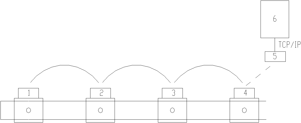
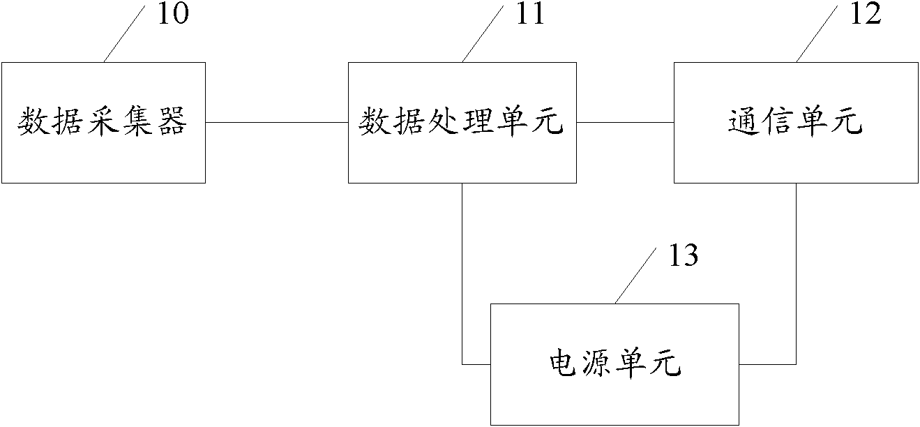
[0127] Step 100, a plurality of intelligent busbar joint units arranged on each busbar joint collect the working state parameters of each busbar respectively, and select the nearest routing path to transmit the collected busbar working state parameters to the intelligent control box; State parameters include busbar temperature, current, voltage and other parameters;

[0128] Step 101, the intelligent control box polls the multiple intelligent bus joint units, and uses single or multiple channels to receive the working status of the busbar from the multiple bus joints transmitted by wireless ad hoc network technology at the same time parameters, and send the received busbar working status parameters to the management device after protocol conversion;

[0129] Step 102, the management device monitors, manages and controls the working state of the bus bar according to the working s...


PUM


Abstract

The invention provides a real-time bus working state monitoring method and an intelligent bus system. The intelligent bus system comprises one or a plurality of intelligent bus connector units which serve as routes with one another and are used for acquiring working state parameters of all busbars, an intelligent control box and a management device, wherein each intelligent bus connector unit transmits the working state parameters acquired by each intelligent bus connector unit to the intelligent control box by selecting a nearest route path; the intelligent control box is used for receiving busbar working state parameters transmitted by the plurality of intelligent bus connector units by using wireless self-networking technology, carrying out protocol conversion on the received busbar working state parameters and then sending the received busbar working state parameters subjected to the protocol conversion to the management device; and the management device is used for monitoring, managing and controlling working states of buses according to the busbar working state parameters. By implementing the method and the system, the technology of monitoring, managing and controlling the working states of the buses through monitoring the working states of the buses in real time and transmitting a monitoring result to a management center in real time is realized.

Description

technical field [0001] The invention relates to the field of electric power technology, in particular to a system and method for real-time monitoring of the working state of a busbar, which is named an intelligent busbar system. Background technique [0002] In the electric power system, due to long-term operation in the air and the influence of ambient temperature and humidity, the busbar joint nodes will experience thermal expansion and contraction, surface scaling, oxidation or corrosion, resulting in loose contacts, poor contact, and abnormal overheating. In serious cases, it may lead to fire or major safety accidents. Traditional busbars do not have detection and alarm functions. However, the existing intelligent busbar system mainly uses two methods to realize it. Signals are transmitted to the management unit via signal lines running along the busbar. The disadvantage of this wired method is that signal wires need to be laid along the entire busbar, which will damage...

Claims


Application Information

Patent Timeline
Patent Type & Authority Applications(China)
IPC IPC(8): H02J13/00
Inventor 丁青青朱静波
Owner 深圳吉天广通科技有限公司
Why Eureka
Try Eureka