
Three-level inverter narrow pulse elimination and midpoint voltage control method and device

A three-level inverter, narrow pulse technology, applied in the field of frequency converters, can solve the problems of easily damaged power switch tubes, system collapse, difficult control of mid-point voltage, etc. The effect of narrow pulses

Active Publication Date: 2015-08-19
SHENZHEN INVT ELECTRIC
View PDF1 Cites 0 Cited by
  • Summary
  • Abstract
  • Description
  • Claims
  • Application Information

AI Technical Summary

Problems solved by technology

Under low modulation coefficient, since the given voltage space vector is close to the zero vector, the conduction time of the small vector is very short, so that there are a large number of narrow pulses in the driving pulse of the power switch tube, which will lead to the output of the three-level inverter The voltage is distorted, the output starting torque is reduced, and the power switch tube is easily damaged
Moreover, since the midpoint potential of the three-level inverter is obtained through capacitor voltage division, the midpoint voltage will shift during the actual operation of the three-level inverter, which will also cause the output of the three-level inverter There is distortion in the voltage, which will lead to the collapse of the whole system in severe cases
[0004] At present, three-level inverters can eliminate narrow pulses by properly inserting zero vectors, but this control method is very complicated, and the midpoint voltage is difficult to control

Method used


Image

  • Three-level inverter narrow pulse elimination and midpoint voltage control method and device
  • Three-level inverter narrow pulse elimination and midpoint voltage control method and device
  • Three-level inverter narrow pulse elimination and midpoint voltage control method and device

Examples


Embodiment Construction

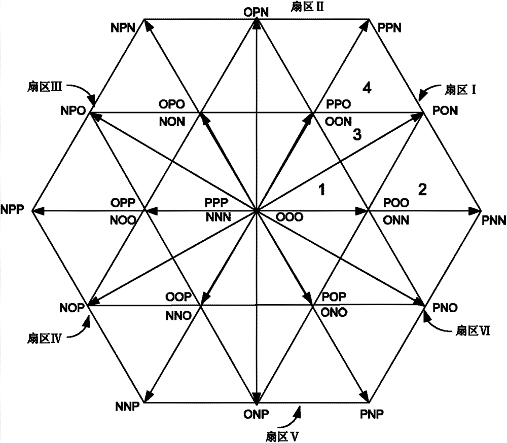
[0042] Three-level inverter, when the output voltage is positive, it is marked as P, when the output voltage is negative, it is marked as N, and when the output voltage is 0, it is marked as O. In this way, each phase can output three levels, three There are 27 output combinations on the phase output line, that is, 27 space vectors. The distribution diagram of these 27 space vectors is as follows: figure 2As shown, 27 space vectors are distributed in 6 sectors in total. The 6 sectors are regular hexagons in the figure, and each sector is a regular triangle, where PPP, NNN, and OOO are zero vectors, and PNN, PPN, NPN, NPP, NNP, PNP are large vectors, PON, OPN, NPO, NOP, ONP, PNO are medium vectors, POO, ONN, PPO, OON, OPO, NON, OPP, NOO, OOP, NNO, POP, ONO is a small vector, and the output voltage of the three-level inverter is close to zero under low modulation coefficients. Therefore, it is obtained by combining the zero vector and the small vector.

[0043] In order to ena...


PUM


Abstract

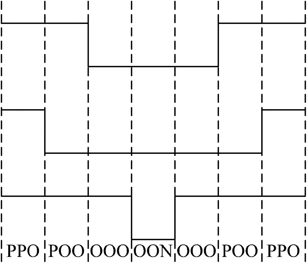
The invention discloses a three-level inverter narrow-pulse elimination and midpoint voltage control method and device. The method comprises the following steps of: judging whether the current given voltage space vector stays at a low modulation factor, if yes, then the resultant vector forming the current given voltage space vector comprises two groups of positive and negative small vectors, starting with a zero vector, and conducting in a thirteen-section type conduction way with only one phase level change every time; or else, conducting in a seven-section type conduction way starting with a small vector; calculating the action time of the resultant vector via the current given voltage space vector; calculating a time control factor according to the obtained midpoint voltage offset and the output current direction; redistributing the action time of positive and negative small vectors according to the conduction time and the time control factor of the resultant vector; and obtaining the driving pulse of a power switch tube in a three-level inverter according to the action time of the redistributed positive and negative small vectors. The narrow pulse is eliminated by using the zero vector, and the midpoint voltage is controlled by using two groups of positive and negative small vectors.

Description

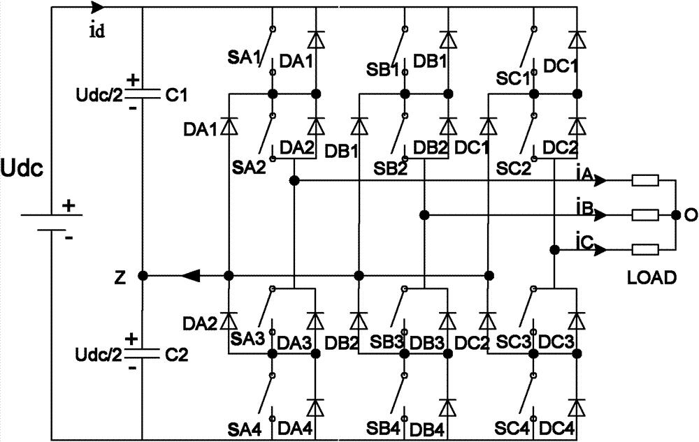
technical field [0001] The present application relates to the technical field of frequency converters, in particular to a method and device for narrow pulse elimination and midpoint voltage control of a three-level inverter. Background technique [0002] The main circuit structure of the three-level inverter is as follows: Figure 1a As shown, it includes three bridge arms of phase A, phase B and phase C, and each bridge arm has 4 power switch tubes in series, 4 freewheeling diodes connected in parallel at both ends of each power switch tube, and two Clamping diodes, as shown in Figure 1, SA1, SA2, SA3 and SA4 are the power switch tubes on the A-phase bridge arm, SB1, SB2, SB3 and SB4 are the power switch tubes on the B-phase bridge arm, SC1, SC2, SC3 and SC4 are the power switch tubes on the C-phase bridge arm; DA1 and DA2 are the clamping diodes on the A-phase bridge arm; DB1 and DB2 are the clamping diodes on the B-phase bridge arm; DC1 and DC2 are the C-phase bridge arms...

Claims


Application Information

Patent Timeline
Patent Type & Authority Patents(China)
IPC IPC(8): H02M7/487H02M7/49
Inventor 刘亚军张波
Owner SHENZHEN INVT ELECTRIC
Learn More