
Method and device for recycling and reusing heat energy of lighting facilities

A technology for lighting facilities and heat recovery, applied in lighting devices, cooling/heating devices for lighting devices, lighting and heating equipment, etc., can solve problems such as mercury pollution, poor color rendering, and insufficient luminous flux

Inactive Publication Date: 2012-07-11
E SWEET TECH CORP
View PDF0 Cites 16 Cited by
  • Summary
  • Abstract
  • Description
  • Claims
  • Application Information

AI Technical Summary

Problems solved by technology

[0003] Among all lighting products, except for LED (diode light-emitting lighting) and CCFL (cold cathode tube lighting) developed in recent years, most of them are lighting devices that consume a lot of power; such as incandescent lamps, halogen lamps, mercury lamps, and high-pressure sodium lamps , ceramic composite metal lamps, etc.; although LED lamps, fluorescent lamps, CCFL lamps, etc. are relatively power-saving, there are still many problems such as poor heat dissipation, serious light decay, and mercury pollution that have not been effectively resolved; moreover, if these lighting devices For outdoor lighting, such as road / street lights, projection lights, stadium or square lighting, or for lighting in factories and stores, there are still problems such as insufficient luminous flux and poor color rendering. Therefore, outdoor lighting, especially street lights, street lights or Most of the wall washer lamps used for advertising are still based on relatively large power consumption ceramic complex metal lamps, high pressure sodium lamps, etc.

Method used


Image

  • Method and device for recycling and reusing heat energy of lighting facilities
  • Method and device for recycling and reusing heat energy of lighting facilities
  • Method and device for recycling and reusing heat energy of lighting facilities

Examples


Embodiment Construction

[0071] Below in conjunction with accompanying drawing, structural principle and working principle of the present invention are specifically described:

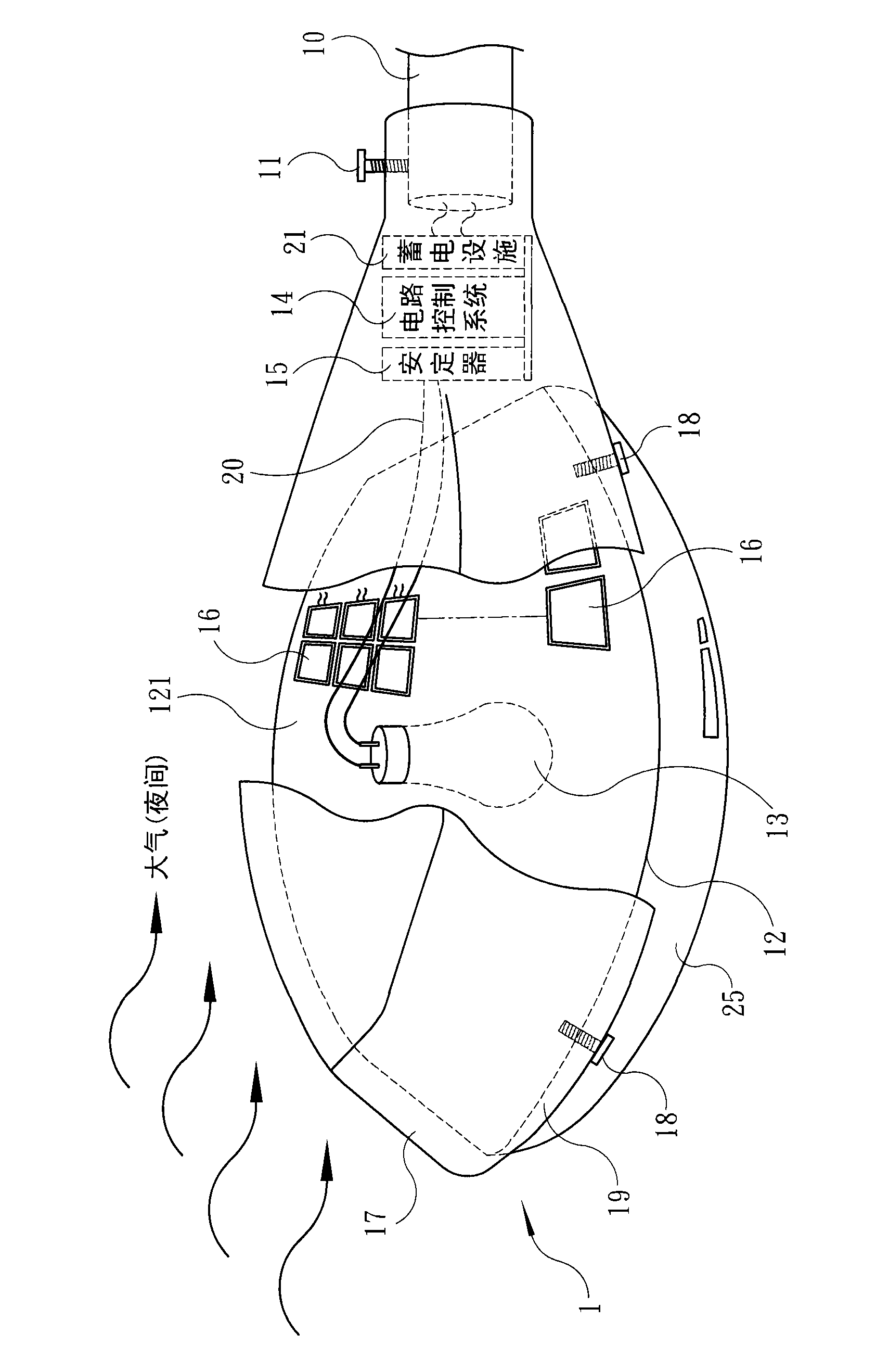
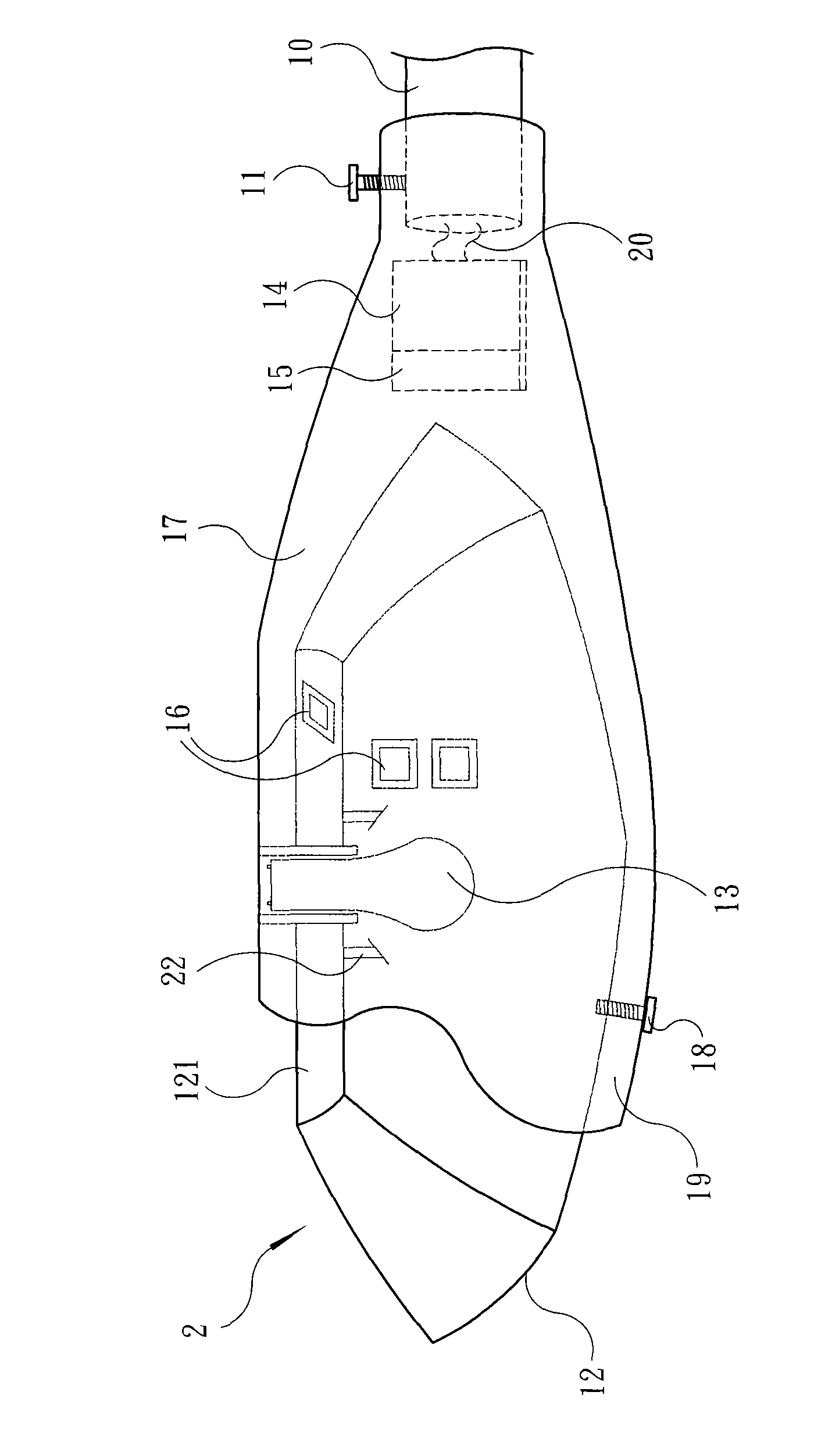
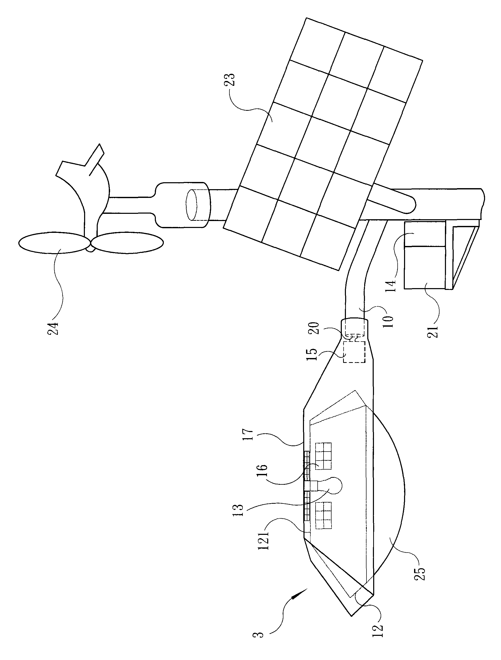
[0072] see figure 1 , the present embodiment is illustrated with a general street lamp. At the end of a light pole 10, a reflector 12, a transparent shield 25, a light source 13, a circuit control system 14, a stabilizer 15, and a thermoelectric chip module 16 arranged on the outer surface 121 of the reflector are installed with fastening screws 11. The light fixture lamp shell 17 of spare parts such as is set firmly. The light source 13 of the present invention can be various products, such as the light bulb 13 shown in this embodiment. Wherein the lamp housing 17 and the reflector 12 are fastened together by fastening bolts 18, and a heat insulating material 19 is placed in the middle spacer to avoid the effect of heat conduction, so that the two can maintain a cold end and a hot end respectively, forming a temperature dif...


PUM


Abstract

The invention discloses a method and device for recycling and reusing heat energy of lighting facilities. The device mainly comprises a thermoelectric chip module, a reflecting cover, a lamp shell, a circuit control system, an electricity-storage facility and other necessary electronic components, wherein the thermoelectric chip module is used for converting heat energy into electrical energy. Through taking heat energy (generated by a light source) as a hot end and taking the lamp shell in contact with the atmosphere as a cold end, the upper and lower ends of the thermoelectric chip module distributed between the reflecting cover and the lamp shell are respectively heated or cooled, and thus a stable temperature difference is formed so as to generate electrical energy, then the obtained electrical energy is stored in the electricity-storage facility through voltage and current control chips and circuit modules and the like in the circuit control system or directly inputted into a power supply circuit; therefore, the purpose of effectively recycling and reusing the heat energy generated by the light source and then further saving electrical energy can be achieved.

Description

technical field [0001] The present invention relates to a method and device for recovering and reusing the heat energy of lighting facilities such as street lamps, and in particular to an energy-saving and light-reducing energy-saving device that can further recycle the heat energy produced by the light source through a thermoelectric chip module and convert it into electric energy for reuse. carbon device. Background technique [0002] Since Edison, the great American inventor, invented the electric light in the 19th century, human beings have enjoyed lights as bright as day in the dark. For more than one hundred years, electric lights have lit up every corner of the world. In addition to providing convenient lighting for human life, they have also greatly improved the efficiency of science and technology and the development of civilization; however, human beings also spent a lot of money in order to obtain lighting. Electricity has gradually led to the nightmare of energy...

Claims


Application Information

Patent Timeline
Patent Type & Authority Applications(China)
IPC IPC(8): H02N11/00F21V29/00H02J7/00F21V29/507
CPCY02B20/72
Inventor 廖明振吕淑云廖珮瑜廖书璇
Owner E SWEET TECH CORP
Learn More