Optical fiber fault detection method and optical fiber fault detection device

A fiber optic fault detection and fault technology, which is applied in the field of optical access, can solve the problems of no fiber fault detection, etc., and achieve the effects of easy implementation, reduced detection cost, and improved detection efficiency

Active Publication Date: 2012-07-11
ZTE CORP
View PDF3 Cites 20 Cited by
  • Summary
  • Abstract
  • Description
  • Claims
  • Application Information

AI Technical Summary

Problems solved by technology

At present, there is no method for detecting fiber optic faults in passive optical networks with integrated PON ports.

Method used


Image

  • Optical fiber fault detection method and optical fiber fault detection device
  • Optical fiber fault detection method and optical fiber fault detection device
  • Optical fiber fault detection method and optical fiber fault detection device

Examples


Embodiment 1

[0038] In this embodiment, for figure 2 The passive optical network shown performs fiber fault detection.

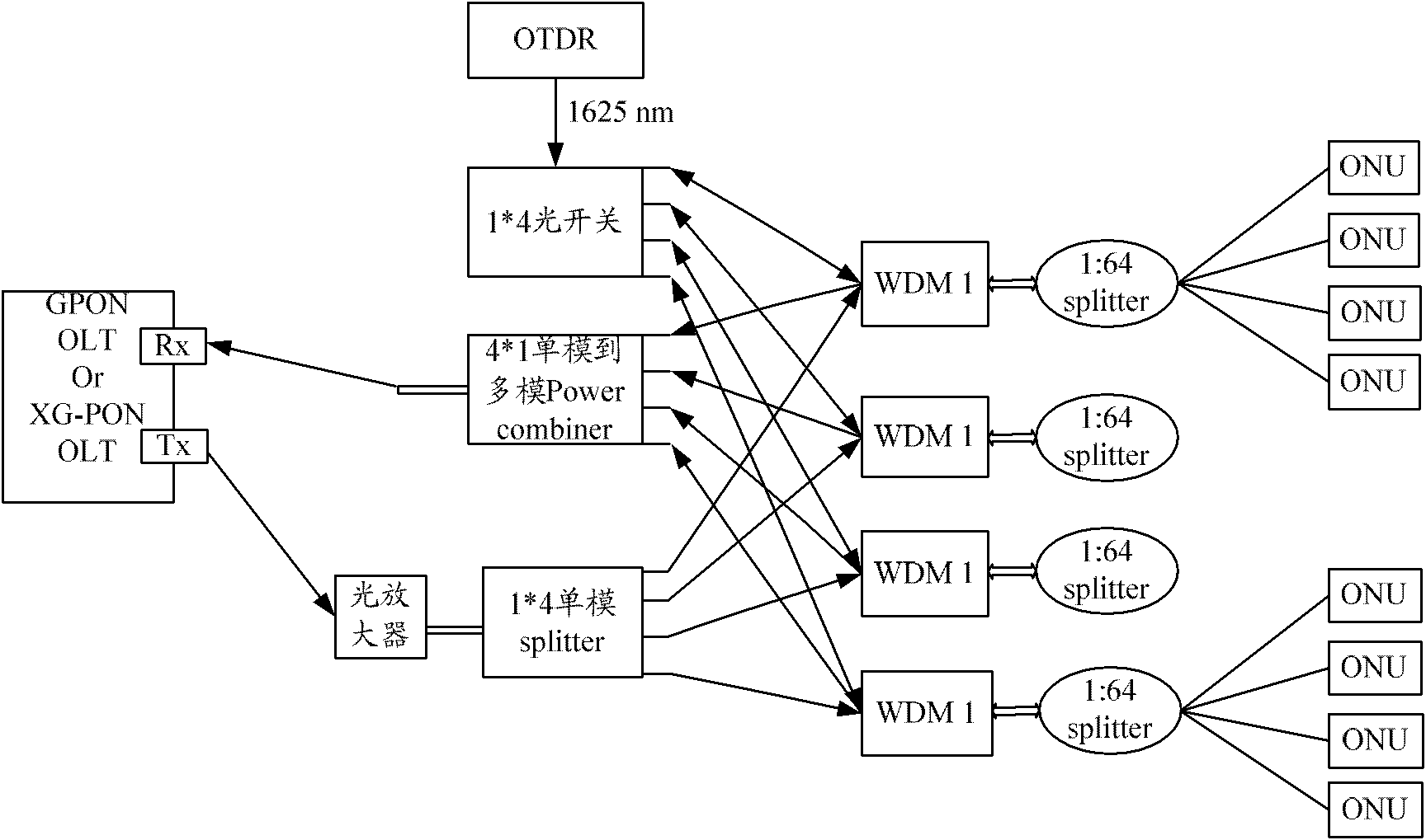
[0039] Such as figure 2 As shown, the passive optical network of this embodiment includes: OLT, optical amplifier, 1*4 single-mode optical splitter, four first WDMs (WDM_1), four 1:64 optical splitters, multiple ONUs, and 4* 1 single-mode to multi-mode mode coupler (mode coupler).

[0040]Among them, the above-mentioned passive optical network can transmit four uplink lights and four downlink lights, and the OLT can be a GPON OLT or an XG-PON OLT, which has a transmitter Tx for outputting downlink light, and a transmitter Tx for receiving uplink light The receiver Rx. Specifically, the four WDM_1 are connected to the mode coupler through a single-mode fiber, the mode coupler is connected to the receiver Rx of the OLT through a multimode fiber, the transmitter Tx of the OLT is connected to the optical amplifier, and the optical amplifier is connected to the 1*4 singl...

Embodiment 2

[0052] In this embodiment, for Figure 5 The passive optical network shown performs fiber fault detection.

[0053] Such as Figure 5 As shown, the passive optical network of this embodiment includes: GPON OLT, XG-PON OLT, S-band optical amplifier, L-band optical amplifier, 2*4 single-mode optical splitter, four first WDMs (WDM_1), four 1:64 optical splitter, multiple ONUs, 4*1 single-mode to multi-mode mode coupler (Power Combiner) and the second WDM (WDM_2).

[0054] Wherein, the composition structure and function of WDM_1 are completely the same as those of WDM_1 in Embodiment 1, and will not be repeated here. The composition structure and function of the mode coupler are also the same as those in the first embodiment.

[0055] WDM_2 is to split the uplink light of different wavelengths. Different from the general filter, the optical path connecting the entrance and exit of it is a multimode optical fiber. According to the existing thin-film filtering technology, WDM_2 ...


PUM


Abstract

The invention discloses an optical fiber fault detection device, which comprises an optical time domain reflectometer (OTDR) and an optical switch, wherein the optical switch is connected between an OTDR and a passive optical network, used for enabling the OTDR to be connected with optical distribution node networks (ODNs) whose number is N in the passive optical network and communicated with the OTDR and the ODNs needing detecting, and N is an integer not smaller than 1. Each ODN in the passive optical network comprises an optical fiber fault detection interface for being connected with the optical switch, and the OTDR is used for performing optical fiber fault detection to the ODNs needing detecting. Correspondingly, the invention further comprises an optical fiber fault detection method. The optical fiber fault detection method is easy to implement, convenient to operate and insusceptible to limitation of testing conditions, avoids interrupting tasks being performed by the passive optical network, can be applied to various passive optical networks, improves optical fiber fault detection efficiency and reduces detection cost.

Description

technical field [0001] The invention relates to the field of optical access, in particular to an optical fiber fault detection method and device. Background technique [0002] With the rapid development of optical fiber communication technology and the requirements of low cost and green environmental protection, the communication network, from the core network, the metropolitan area network to the access network, all uses optical fiber to form a network. [0003] Since the number of users that can be connected to each passive optical network (PON, Passive Optical Network) port is limited, it is often necessary to increase the PON port to meet the needs in a densely populated community or when more users need to be connected to a PON. [0004] In order to solve the problem that the number of users that can be connected to the PON port is limited, the mode coupler can also be used to combine the PON ports to improve the efficiency of the PON port and reduce operating costs. A...

Claims


Application Information

Patent Timeline
Patent Type & Authority Applications(China)
IPC IPC(8): H04B10/08H04Q11/00H04B10/071
CPCH04B10/07H04B10/071H04B10/272
Inventor 付志明徐继东
Owner ZTE CORP
Why Eureka
Try Eureka