Method and system for indoor positioning

An indoor positioning and positioning terminal technology, applied in electrical components, wireless communication and other directions, can solve the problems of large fluctuation of signal strength and reduced matching accuracy, and achieve the effect of rigorous matching process, improved matching accuracy, and full use of beacons

Active Publication Date: 2012-07-11
BEIJING RTMAP TECH
View PDF4 Cites 100 Cited by
  • Summary
  • Abstract
  • Description
  • Claims
  • Application Information

AI Technical Summary

Problems solved by technology

[0006] However, the above-mentioned matching positioning algorithm based on sampling points has disadvantages. The matching of positioning data calculates the distance between all sampling points and a

Method used


Image

  • Method and system for indoor positioning
  • Method and system for indoor positioning
  • Method and system for indoor positioning

Examples


Embodiment 1

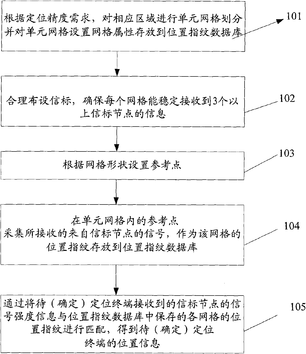
[0021] An embodiment of the present invention provides an indoor positioning method, see figure 1 The method includes the following steps:

[0022] Step 101: According to the requirement of positioning accuracy, divide the corresponding area into unit grids and set grid attributes for the unit grids, and store them in the location fingerprint database;

[0023] Step 102: rationally arrange beacon nodes to ensure that each grid can receive information from more than 3 beacon nodes;

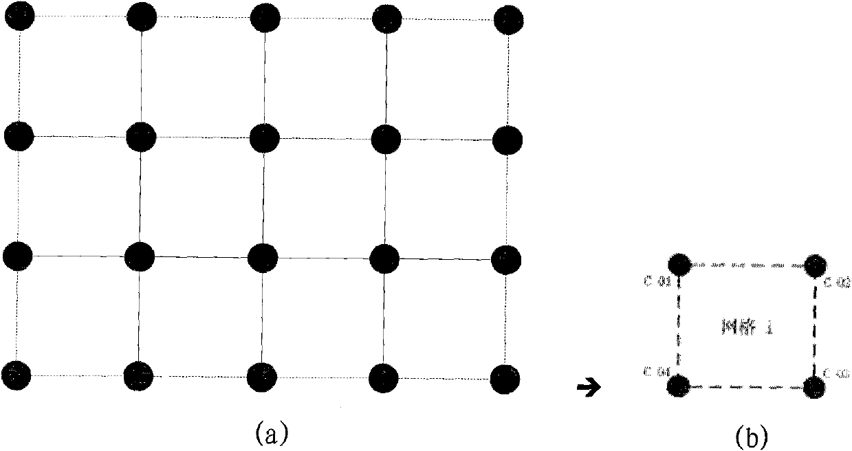
[0024] Step 103: According to the shape of the grid, each vertex of the grid is used as the reference point of the grid, such as image 3 ;

[0025] Step 104: collect the received signal from the beacon node at each reference point of the unit grid, and store it in the location fingerprint database as the location fingerprint of the grid;

[0026] Step 105: During positioning, match the signal strength of the beacon node received by the terminal to be positioned with the corresponding reference ...

Embodiment 2

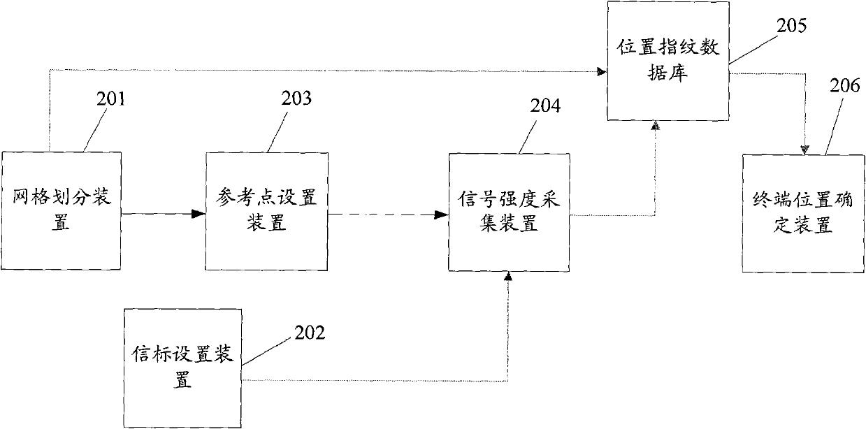
[0056] An embodiment of the present invention provides an indoor positioning system, see figure 2 , the system includes: a grid division device 201 , a beacon setting device 202 , a reference point setting device 203 , a signal strength collecting device 204 , a location fingerprint database 205 and a terminal location determining device 206 .

[0057] Wherein, the grid division device 201 is used to perform unit grid division on the corresponding indoor area according to the positioning accuracy requirements, and store the grid information into the location fingerprint database;

[0058] The beacon deployment device 202 is used to deploy multiple beacon nodes to ensure that there is a certain difference in received signal strength in each grid;

[0059] Reference point determining means 203, configured to determine a plurality of reference points in the unit grid, and collect the signal strength of the beacon node received at the reference point as a fingerprint and store it...


PUM


Abstract

The invention discloses a method and a system for indoor positioning, relating to a wireless communication network, in particular to the method and the system for indoor positioning. The method comprises the following steps of: dividing unit grids of corresponding regions, and setting grid attributes of the unit grids; laying out beacon nodes according to a receiving signal situation in the unit grids; setting a plurality of reference points according to the forms of the unit grids, acquiring signal strength of each beacon node at each reference point, calculating the statistic of the signal strength as a position fingerprint, and storing the position fingerprint to a position fingerprint database; calculating the statistic of the signal strength of the beacon node received by a terminal to be positioned, matching with the position fingerprints corresponding to all the grids in the position fingerprint database, and thus acquiring the most similar grids; and determining the position information of the terminal to be positioned. The matching accuracy can be improved through grid division; the system is moved in a rotating manner in all directions during acquisition, and incomplete characteristic values caused by unidirectional acquisition are prevent; and beacons are reasonably laid out, so that redundant equipment is saved and the beacons are fully used.

Description

technical field [0001] The invention relates to a wireless communication network, in particular to an indoor positioning method and system. Background technique [0002] With the development and popularization of WLAN (Wireless Local Area Network, wireless local area network) and WSN (Wireless Sensor Network, wireless sensor network), the application of indoor positioning in business, public safety and military has become a research hotspot, such as deploying WSN in industrial On-site, monitor the operation of equipment, deploy in warehouses to track logistics dynamics, and even temporarily deploy quickly at fire rescue sites to provide firefighters with optimal route navigation. Based on existing hardware facilities such as WLAN and Wi-Max (worldwide interoperability for microwave access, universal microwave communication technology) that are widely used, there are also many attempts to provide various indoor positioning services by adding software modules. [0003] Since ...

Claims


Application Information

Patent Timeline
IPC IPC(8): H04W64/00
Inventor 邓中亮徐连明朱宇佳刘文龙李欣欣方灵盛庆崔艳雯孙子砚王珂毕乾刘晨史丹丹裘昕
Owner BEIJING RTMAP TECH
Why Eureka
Try Eureka