Pipe cutting machine

A technology of pipe cutting machine and cutting machine, applied in the direction of pipe shearing device, shearing device, shearing machine equipment, etc., can solve the problems of operator burns, larger and rougher blade diameter, etc., to achieve firm maintenance and low cutting noise Effect

Inactive Publication Date: 2014-05-14
车永俊
View PDF4 Cites 2 Cited by
  • Summary
  • Abstract
  • Description
  • Claims
  • Application Information

AI Technical Summary

Problems solved by technology

[0002] Generally, the well-known pipe cutting machine is to fix the pipe to be cut behind the cutting plate and make it contact with the cutting blade rotating at high speed. At this time, the cutting knife vertically passes through the pipe and cuts at a high speed. However, the described method has the following advantages: The following problems, that is, when the diameter of the pipe is large, the diameter of the blade also becomes larger accordingly, and, since a lot of cutting debris occurs during the cutting process, especially the cutting debris flies toward the operator's side, causing burns to the operator, not only There is a lot of noise during cutting, and the surface to be cut becomes vertical and becomes rough, resulting in reinforcement, so it is necessary to remove the reinforcement.

Method used


Image

  • Pipe cutting machine
  • Pipe cutting machine
  • Pipe cutting machine

Examples


Embodiment Construction

[0051] Hereinafter, a pipe cutting machine according to the present invention will be described with reference to the accompanying drawings. First, the same symbols are assigned to the same constituent elements or components in the drawings. When describing the present invention, in order to clarify the gist of the present invention, specific descriptions of related known functions or configurations are omitted.

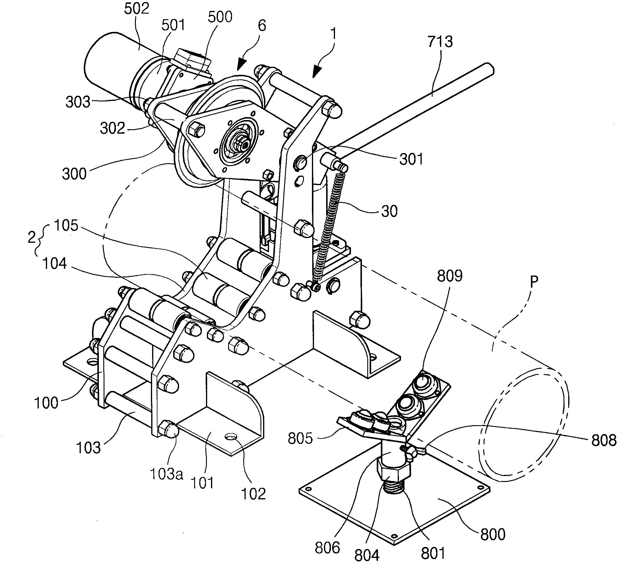
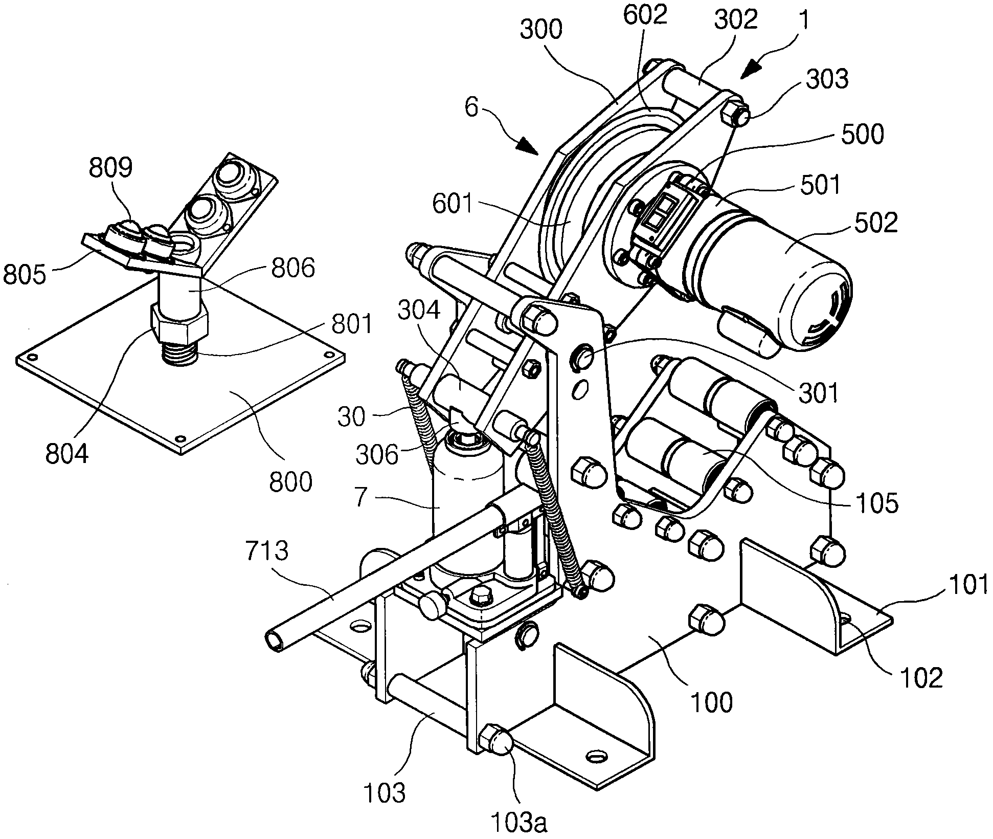
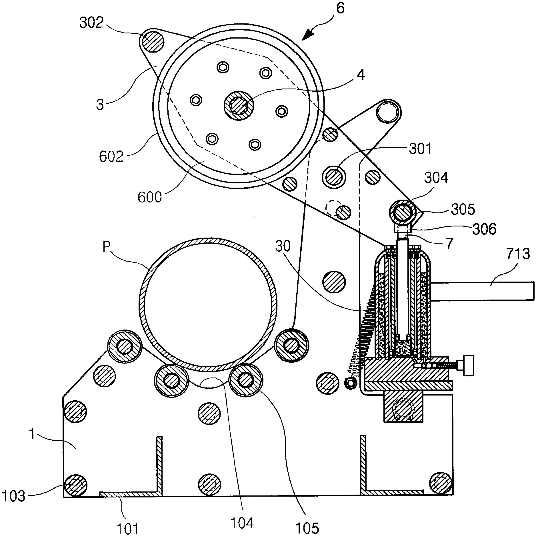
[0052] figure 1 is an overall perspective view showing the present invention, figure 2 It is a perspective view showing the back side, image 3 It is a vertical side view.

[0053] and, Figure 4 yes image 3 The action state diagram of Figure 5 is an exploded perspective view of the sub-chassis according to the present invention, Figure 6 is a sectional view illustrating the cutter portion of the present invention, Figure 7 yes Figure 6 exploded perspective view.

[0054] Figure 8 is a sectional view of the hydraulic jack part of the present inventi...


PUM


Abstract

The present invention relates to a pipe cutting machine. The pipe cutting machine of the present invention comprises: a cutting machine body having a cutting board where a pipe to be cut is placed; a pipe mount, which has a mount groove formed in such a manner that the pipe to be cut is mounted thereon in the horizontal direction and includes roller bearings arranged at regular intervals at the inner surface of the mount groove, thereby enabling in-place rotation of the pipe at the mount groove once the pipe to be cut is placed thereon; a rotary blade mount, which includes a hinge shaft installed at the upper side of the pipe mount and a support shaft coupled to the hinge shaft to make a see-saw motion; a motor for driving the rotary blade disposed at the front end side of the rotary blade mount; a piston of a manual hydraulic jack connected to the opposite end to where the rotary blade is disposed, for moving the rotary blade in the vertical direction; and a pipe auxiliary base having an adjustable height disposed at the side of the pipe mount. As such, the pipe is cut as the rotary blade comes in contact with the pipe disposed at the cutting blade and pivots.

Description

technical field [0001] The present invention relates to a pipe cutting machine and more particularly to placing the pipe to be cut on a pipe mount mounted with ball bearings and then bringing a rotary knife formed with a blade formed around a disc into contact perpendicularly to the surface of the pipe , Press down from above, so that the surface of the tube contacts the rotating knife, and the tube rotates with the rotation of the rotary knife to be cut by the tube cutting machine. Background technique [0002] Generally, the well-known pipe cutting machine is to fix the pipe to be cut behind the cutting plate and make it contact with the cutting blade rotating at high speed. At this time, the cutting knife vertically passes through the pipe and cuts at a high speed. However, the described method has the following advantages: The following problems, that is, when the diameter of the pipe is large, the diameter of the blade also becomes larger accordingly, and, since a lot o...

Claims


Application Information

Patent Timeline
Patent Type & Authority Patents(China)
IPC IPC(8): B23D21/04B23D21/00B23D17/06B23D17/04
CPCB23D21/00
Inventor 车永俊
Owner 车永俊
Why Eureka
Try Eureka