Button-type rapid air exhaust one-way air valve

A one-way air valve and exhaust valve technology, applied in the direction of cardiac catheterization, etc., can solve the problems of inconvenient operation, difficult to unscrew the exhaust, troublesome operation of opening and closing the knob, etc., to achieve simple and convenient operation and overcome the inconvenience of operation Effect

Inactive Publication Date: 2013-12-11
刘忠发
View PDF10 Cites 2 Cited by
  • Summary
  • Abstract
  • Description
  • Claims
  • Application Information

AI Technical Summary

Problems solved by technology

[0002] The sphygmomanometer is a medical device for measuring the blood pressure of the human body. When the sphygmomanometer is working, the air pump inflates the cuff tied to the arm through the one-way valve, and the air in the cuff is discharged through the one-way valve after the measurement is completed. The one-way air valve in the prior art is a knob-type one-way air valve. The knob-type one-way air valve is provided with an opening and closing knob that is opened and closed by a screw. The valve is one-way ventilation, and the compressed air provided by the air pump inflates the cuff in one direction; when exhausting, turn the opening and closing knob in the opposite direction to loosen, the one-way air valve is exhausted to the outside, and the compressed air stored in the cuff passes through the opening and closing knob The opening and closing of the opening and closing knob is very troublesome in practical applications, and it is difficult to unscrew the opening and closing to exhaust from time to time. Therefore, the prior art has the problem and deficiency of inconvenient operation.

Method used


Image

  • Button-type rapid air exhaust one-way air valve
  • Button-type rapid air exhaust one-way air valve
  • Button-type rapid air exhaust one-way air valve

Examples


Embodiment Construction

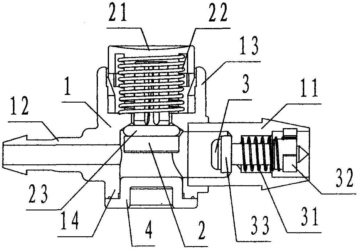
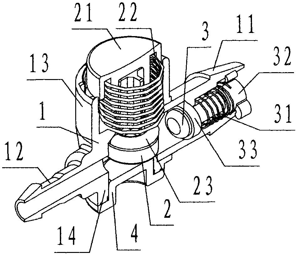
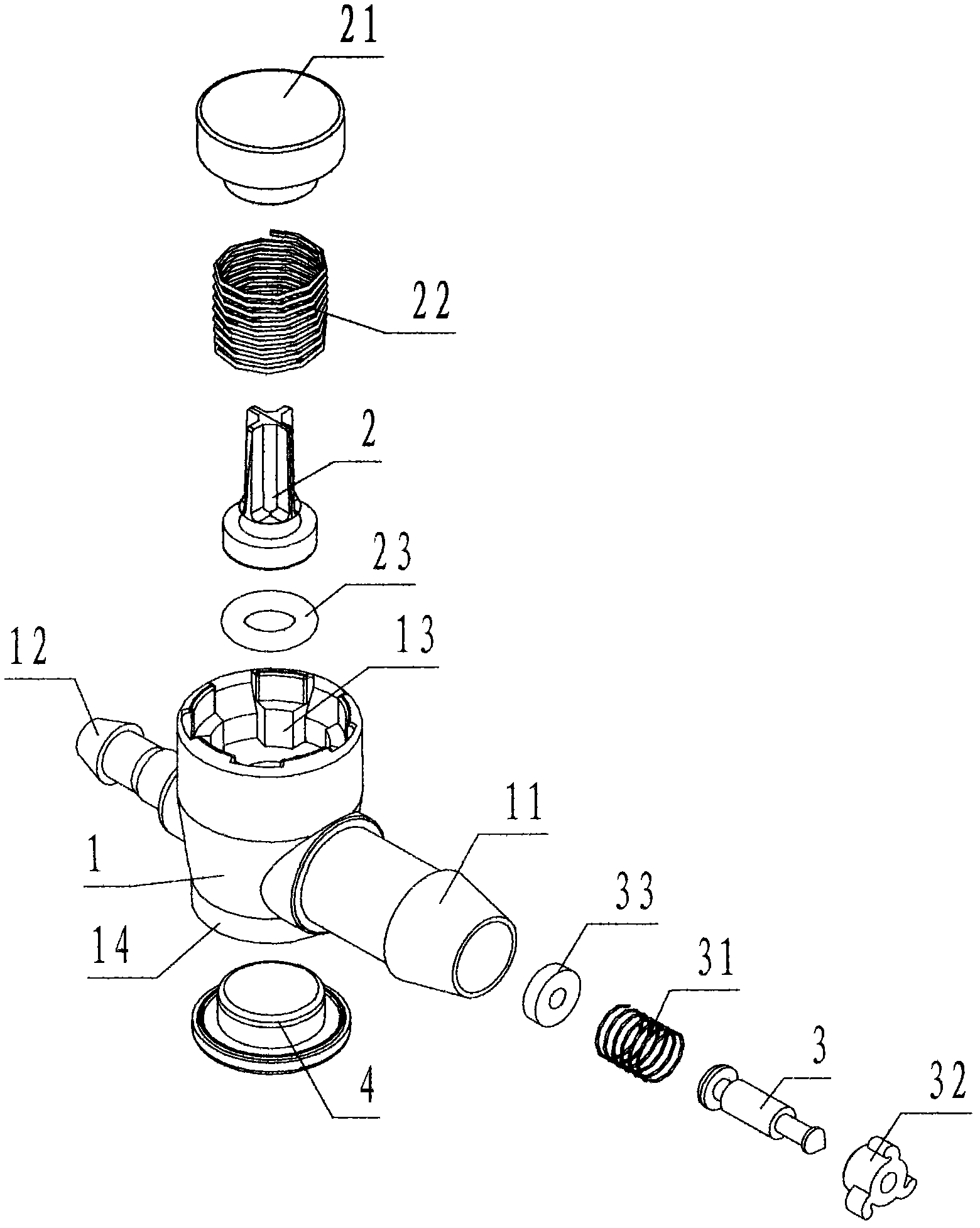
[0021] refer to Figure 1 ~ Figure 3 , a button-type rapid exhaust one-way air valve of the present invention, including a valve body 1, an exhaust valve core 2, an exhaust button 21, a one-way valve core 3, and a plug 4, wherein: the valve body 1 It is a hollow thin-walled plastic shell member in the shape of a four-way pipe; the upper part of the valve body 1 is an exhaust port 13, and the exhaust port 13 is equipped with an embedded exhaust valve core 2, an exhaust button 21, a reset The counterbore steps of the spring 22 and the A sealing ring 23; the hole wall of the exhaust port 13 is evenly provided with a number of exhaust grooves parallel to the axis of the exhaust port 13; the lower part of the valve body 1 is provided with a 2. A process hole 14 for purposes; the left side of the valve body 1 is provided with a hose-shaped air outlet 12; the right side of the valve body 1 is provided with a hose-shaped air inlet 11, and the air inlet 11 is provided with an embedded ...


PUM


Abstract

The invention discloses a button-type rapid air exhaust one-way air valve which comprises a valve body (1), an air exhaust valve core (2), an air exhaust button (21), a one-way valve core (3) and an end cap (4). According to the invention, an air inlet and an air outlet are respectively arranged at the left end and the right end of the valve body; an air exhaust opening is arranged on the upper part of the valve body; the air exhaust opening is internally provided with a pressing air exhaust mechanism composed of an air exhaust valve core, an air exhaust button, a resetting spring and a seal ring A; the air inlet is internally provided with a one-way non-return air inlet mechanism composed of a one-way valve core, a spring, a ventilation clamping ring and a seal ring B; during air inflation, compressed air passes through the valve body unidirectionally to enter a cuff from the air inlet through the air outlet; and during air exhaust, the air exhaust button is pressed to drive the air exhaust valve downward, thus the air outlet is communicated with atmosphere, through the technical scheme that air in the cuff is exhausted from the air outlet through the air exhaust opening, the air charge and discharge of the cuff of a sphygmomanometer achieves the aim of simple, convenient and rapid operation in the mode of pressing exhaust air.

Description

technical field [0001] The invention relates to an air valve, in particular to a button-type rapid exhaust one-way air valve used to control the air pump of the sphygmomanometer to charge and deflate the cuff of the sphygmomanometer. Background technique [0002] The sphygmomanometer is a medical device for measuring the blood pressure of the human body. When the sphygmomanometer is working, the air pump inflates the cuff tied to the arm through the one-way valve, and the air in the cuff is discharged through the one-way valve after the measurement is completed. The one-way air valve in the prior art is a knob-type one-way air valve. The knob-type one-way air valve is provided with an opening and closing knob that is opened and closed by a screw. The valve is one-way ventilation, and the compressed air provided by the air pump inflates the cuff in one direction; when exhausting, turn the opening and closing knob in the opposite direction to loosen, the one-way air valve is e...

Claims


Application Information

Patent Timeline
Patent Type & Authority Patents(China)
IPC IPC(8): A61B5/0235
Inventor 刘忠发
Owner 刘忠发
Why Eureka
Try Eureka