Eureka AIR delivers breakthrough ideas for toughest innovation challenges, trusted by R&D personnel around the world.

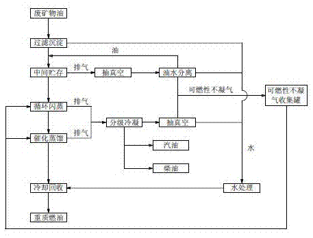
Waste mineral oil cycle flash evaporation catalytic cracking recovery process

A waste mineral oil, catalytic cracking technology, applied in the direction of only multi-stage series refining and cracking process, dehydration/demulsification by mechanical method, etc., can solve the pollution of tail gas emission, waste of energy and water resources, and low recovery efficiency And other issues

Inactive Publication Date: 2016-03-30
云南新昊环保科技有限公司
View PDF5 Cites 2 Cited by
  • Summary
  • Abstract
  • Description
  • Claims
  • Application Information

AI Technical Summary

Problems solved by technology

[0003] Aiming at the deficiencies of the prior art, the present invention provides a method for recovering waste water and waste gas and making full use of it, protecting the environment, saving energy, safe storage, low circulation flash evaporation and catalytic cracking temperature, sufficient separation of light components, small amount of catalyst, and reduced The waste mineral oil circulation flash catalytic cracking recovery process with cracking loss of light components, high recovery rate and low production cost effectively solves the problem of unsafe storage of raw materials, low recovery efficiency, high cost and problems in the recovery and production of waste mineral oil. Waste of energy and water resources, exhaust emissions and environmental pollution

Method used


Image

  • Waste mineral oil cycle flash evaporation catalytic cracking recovery process

Examples


Embodiment 1

[0021] Such as figure 1 Shown, waste mineral oil circulating flash catalytic cracking recovery process, comprises the following steps:

[0022] A. Filtration and sedimentation: put the waste mineral oil into the filtration sedimentation tank and pass through 80-100 mesh filter screen to filter and settle for 2-7 days. to water treatment equipment.

[0023] B. Intermediate storage: vacuumize the oil storage tank with a vacuum degree of -0.01MPa, and separate the extracted gas from oil and water, return the separated oil to the oil storage tank, send the water to the water treatment equipment, and send the flammable non-condensable gas to the storage tank. To the flammable non-condensable gas collection tank.

[0024] C. Circulation flash evaporation: Put the waste mineral oil in the oil storage tank into the flash tank. When the waste mineral oil reaches a certain amount, run the circulation pump, gas heating furnace and vacuum pump to remove the waste mineral oil in the fla...

Embodiment 2

[0029] The waste mineral oil circulation flash catalytic cracking recovery process includes the following steps:

[0030] A. Filtration and sedimentation: put the waste mineral oil into the filtration sedimentation tank and pass through 80-100 mesh filter screen to filter and settle for 2-7 days. to water treatment equipment.

[0031] B. Intermediate storage: vacuumize the oil storage tank, the vacuum degree is -0.02MPa, and separate the oil and water from the extracted gas, return the separated oil to the oil storage tank, send the water to the water treatment equipment, and send the flammable non-condensable gas To the flammable non-condensable gas collection tank.

[0032] C. Circulation flash evaporation: Put the waste mineral oil in the oil storage tank into the flash tank. When the waste mineral oil reaches a certain amount, run the circulation pump, gas heating furnace and vacuum pump to remove the waste mineral oil in the flash tank. Circulating flash evaporation for...


PUM


Abstract

The invention relates to a waste mineral oil recovery process, and especially relates to a waste mineral oil cycle flash evaporation catalytic cracking recovery process comprising the following steps: A, filtering precipitation; B, intermediate storage; C, cycle flash evaporation; D, catalytic distillation; and E, cooling recovery. The process recycles waste water and waste gas, makes full use of the waste water and the waste gas, and has the advantages of environmental protection, energy saving, safe storage, low cycle flash evaporation and catalytic cracking temperatures, full separation of light components, small amount of a catalyst, reduction of cracking loss of the light components, high recovery rate, and low production cost.

Description

technical field [0001] The invention relates to a waste mineral oil recovery process, in particular to a waste mineral oil circulation flash catalytic cracking recovery process. Background technique [0002] When using waste mineral oil as raw material to process and produce waste oil for fuel oil, waste mineral oil contains impurities such as metal scraps, dust, sand, and fibrous substances and moisture, and the impurities are removed after filtration and precipitation. Remove water, flash catalytic cracking, and fractionate gasoline, diesel and heavy fuel oil according to different vaporization points. However, the waste mineral oil after filtration and precipitation still contains water. During the raw material storage process, due to temperature and other reasons, the water in the waste mineral oil will evaporate, and there will be light combustible gas after cracking, and the pressure of the raw material storage tank will decrease. increase, prone to safety accidents. ...

Claims


Application Information

Patent Timeline
Patent Type & Authority Applications(China)
IPC IPC(8): C10G55/06C10G33/06
CPCC10G55/06C10G33/06
Inventor 彭正良
Owner 云南新昊环保科技有限公司
Why Eureka
Eureka Blog
Learn More