Molding device of lost-mold white mold

A molding device and technology of lost foam, applied in the direction of casting molding equipment, etc., can solve problems such as long drying time of white molds, ulceration of hands and feet of operators, and high water content in the core of white molds, so as to solve the problem of unstable molding quality and improve Production environment, the effect of shortening the production cycle

Pending Publication Date: 2020-02-28
十堰众柴发动机部件制造有限公司
View PDF0 Cites 1 Cited by
  • Summary
  • Abstract
  • Description
  • Claims
  • Application Information

AI Technical Summary

Problems solved by technology

[0004] In the prior art, the mixing pipe (water, steam, compressed air) connecting the forming solid plate and the lower mold, after the water is cooled, the remaining water in the mixing pipe cannot be discharged until the steam enters the next mold, and then enters the mold cavity together with the steam The water content in the core of the white mold will be large, resulting in a long drying time of the white mold and a waste of energy;
[0005] In the prior art, the water in the upper touch cavity cannot be completely discharged when the mold is opened, and the cooling water is sprayed several meters away when the mold is opened, and the operators wear waterproof equipment all year round, resulting in ulceration of the hands and feet of the operators;
[0006] In the prior art, after the heating in the mold cavity is completed, the steam is directly discharged into the workshop, resulting in the bad environment of the workshop surrounded by smog;
[0007] In the prior art, the upper and lower molds are connected to solve the drainage problem of the upper mold. When the upper mold is heated, a part of the steam penetrates from the air plug through the foam beads to the lower mold, and the other part of the steam directly enters the lower mold through the connecting hole of the upper and lower molds. The steam cannot be completely To penetrate

Method used


Image

  • Molding device of lost-mold white mold
  • Molding device of lost-mold white mold
  • Molding device of lost-mold white mold

Examples


Embodiment Construction

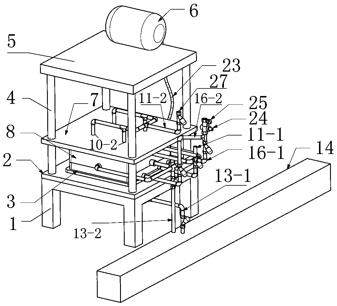
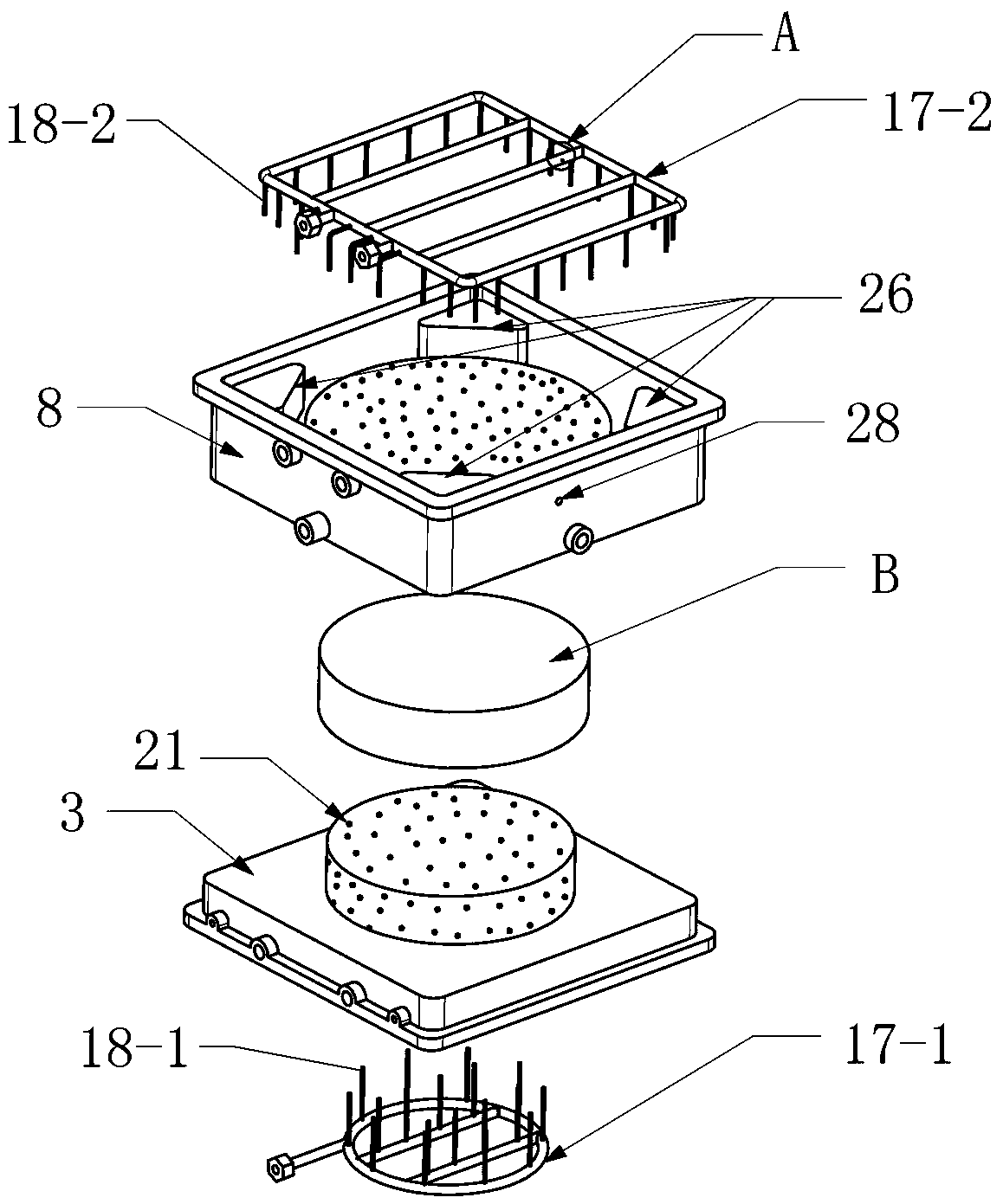
[0035] The technical solutions of the present invention will be clearly and completely described below in conjunction with the accompanying drawings. In the description of the present invention, it should be noted that the terms "center", "upper", "lower", "left", "right", front", "rear", "vertical", "horizontal", "inner" ", "outside" and other indicated orientations or positional relationships are based on the orientations or positional relationships shown in the drawings, which are only for the convenience of describing the present invention and simplifying the description, rather than indicating or implying that the referred device or element must have a specific Orientation, construction and operation in a specific orientation, and therefore should not be construed as limiting the invention. In addition, the terms "first", "second", and "third" are used for descriptive purposes only, and should not be interpreted as indicating or implying relative Right to the importance. ...


PUM


Abstract

The present invention discloses a molding device of a lost-mold white mold, and the molding device includes a bracket, a molding fixing plate fixed to the bracket, a fixing mold fixed to the middle ofthe molding fixing plate, and a plurality of vertical upward guide posts arranged on the molding fixing plate, wherein a top plate is fixed to the tops of the guide posts and provided with a silo, aforming moving plate is connected to the guide posts in sliding, a moving mold is fixed to the bottom of the forming moving plate and opposite to the fixing mold; the fixing mold and the moving mold are respectively provided with a separate air chamber in which separate steam inlets and drainage ports for draining water and steam are arranged; the drainage ports are connected to a sealed drainageditch through a pipe; the fixing mold and the moving mold are respectively provided with a spray cooling pipe; the spray cooling pipe is extended into each part of a chamber wall; and a plurality of air plugs are arranged on the chamber wall between the air chambers of the fixing mold and the moving mold and the chamber. The present invention is a technical innovation in the molding field of the lost-mold white mold and solves the problem that the core of the white mold contains water and the molding quality of large and medium-sized complex parts is unstable, and the production cycle is shortened.

Description

technical field [0001] The invention relates to the field of lost foam casting molding, in particular to a forming device for a lost foam white mold. Background technique [0002] With the widespread use of lost foam casting in the foundry industry, especially the deformation of large and medium-sized parts is relatively obvious. However, in the prior art, the molding quality of parts with complex structures is not good, and the deformation of the white mold is serious. [0003] In the process of realizing the present invention, the inventors found that there are at least the following problems in the existing lost foam casting molding: [0004] In the prior art, the mixing pipe (water, steam, compressed air) connecting the forming solid plate and the lower mold, after the water is cooled, the remaining water in the mixing pipe cannot be discharged until the steam enters the next mold, and then enters the mold cavity together with the steam The water content in the core of...

Claims


Application Information

Patent Timeline
IPC IPC(8): B22C7/02
CPCB22C7/023
Inventor 蒋培堂郭金生孙勇李磊
Owner 十堰众柴发动机部件制造有限公司
Why Eureka
Try Eureka