Bidirectional double-punching can body drawing machine

A technology for stretching machines and tanks, which is applied to stamping machines, presses, and other household appliances, etc. It can solve the problems of high design requirements for dynamic and static pressure bearings, large impact loads, and short service life, so as to reduce the use and maintenance costs , prolong service life and reduce energy consumption

Active Publication Date: 2012-07-18
SUZHOU SLAC PRECISION EQUIP CO LTD
View PDF8 Cites 23 Cited by
  • Summary
  • Abstract
  • Description
  • Claims
  • Application Information

AI Technical Summary

Problems solved by technology

[0007] The invention provides a two-way double-flushing can body stretching machine, which aims to solve the problem that the traditional unidirectional single-flush can body stretching structure has high impact loads on t

Method used


Image

  • Bidirectional double-punching can body drawing machine
  • Bidirectional double-punching can body drawing machine
  • Bidirectional double-punching can body drawing machine

Examples


Embodiment 1

[0054] Example 1: A two-way double-flushing can body stretching machine

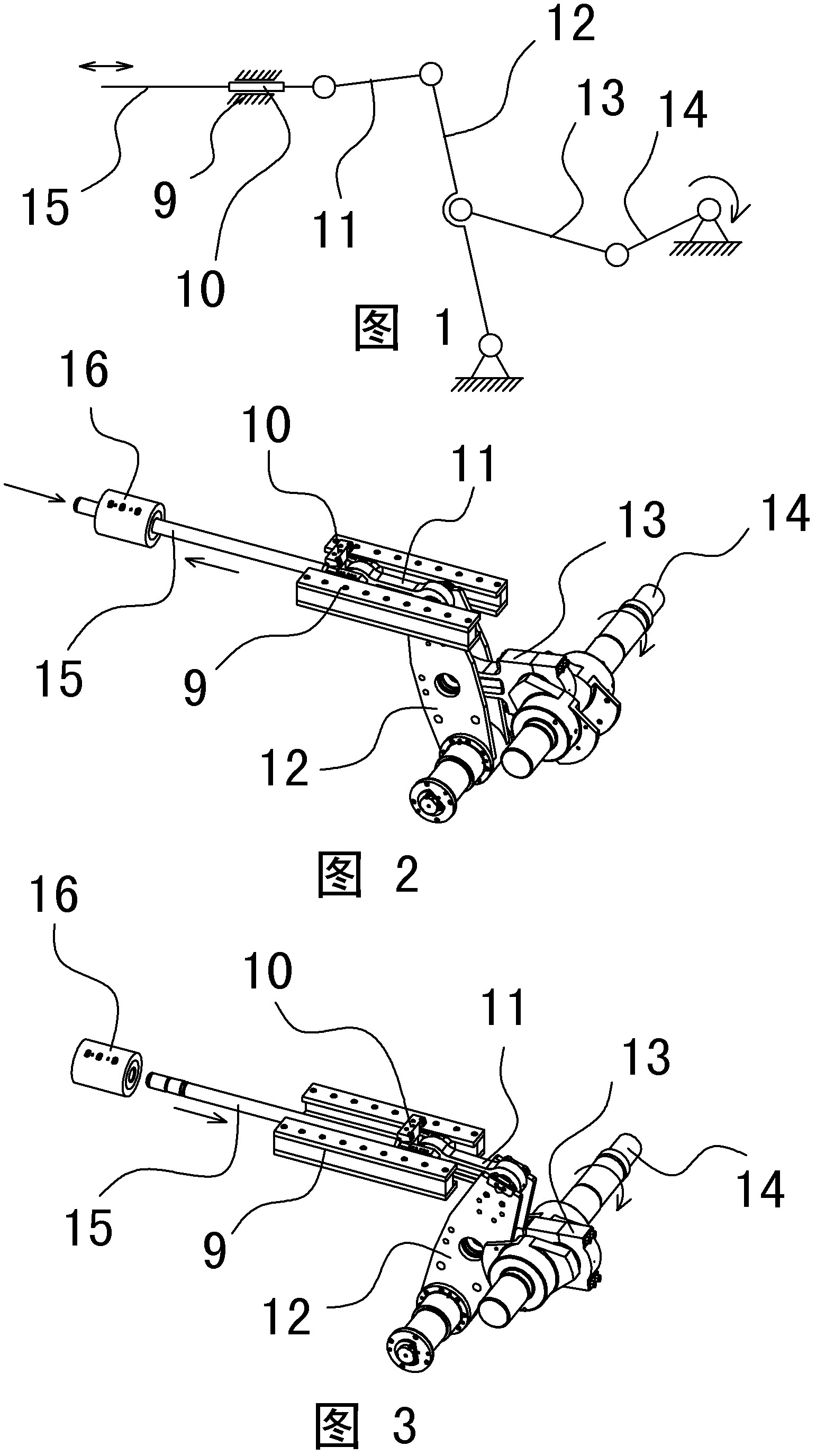
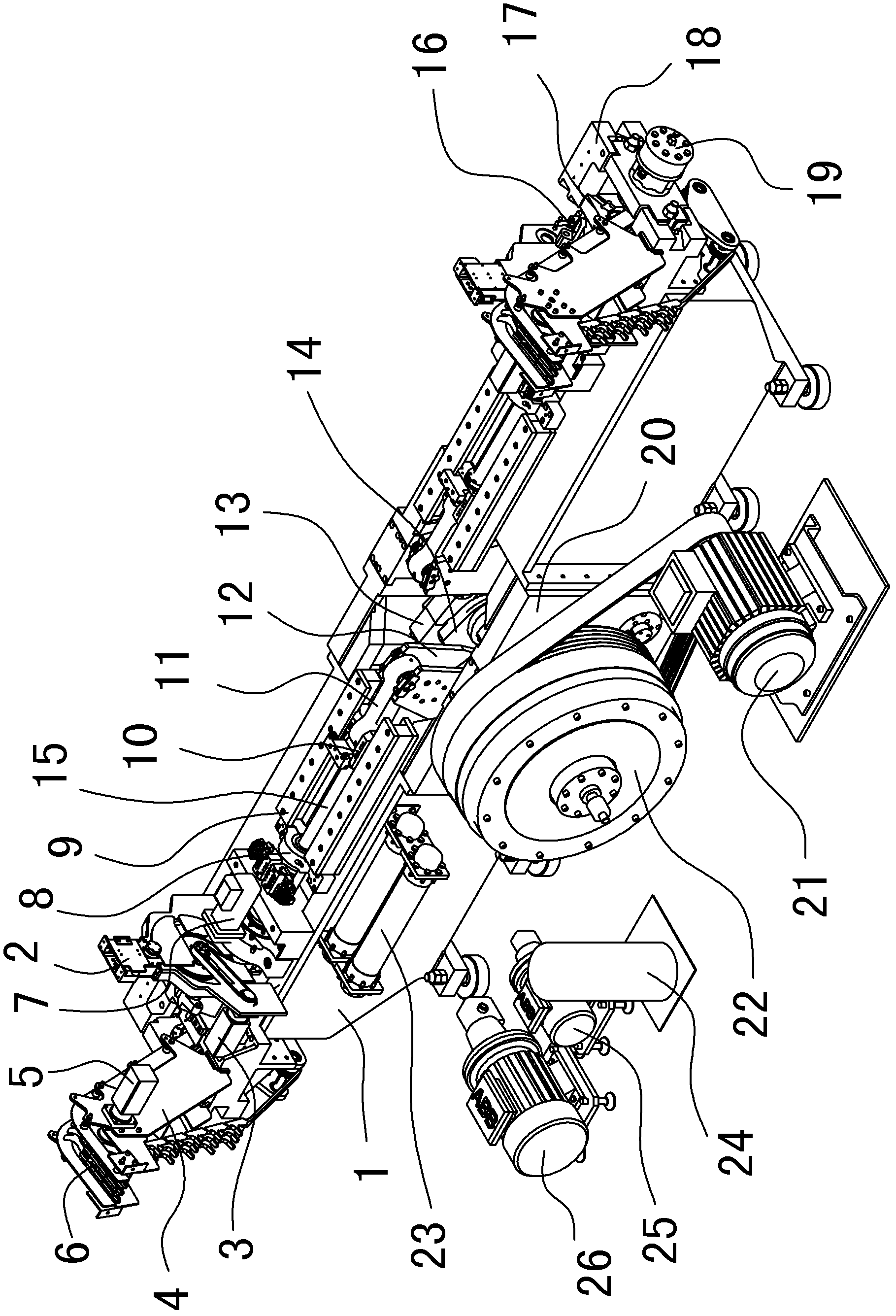
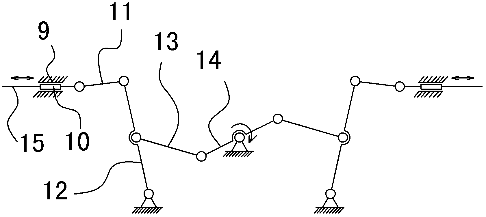
[0055] Such as Figure 4 As shown, the can stretching machine is composed of a box body 1, two sets of molds 16, two sets of crimping mechanisms 7, two sets of cup-inlet mechanisms 2, two sets of can-exit mechanisms 4 and a punch driving mechanism.

[0056] Such as Figure 5 and Figure 8 As shown, the punch driving mechanism consists of the following structures:

[0057] A crankshaft 14, the crankshaft 14 is rotatably supported by a bearing, and the supporting bearing adopts a dynamic and static pressure bearing. The crankshaft 14 is provided with a first crank throw and a second crank throw (see Figure 6 and Figure 7 ), the turning directions of the first crank throw and the second crank throw in the radial direction of the crankshaft 14 are opposite;

[0058] Two identical main links 13, i.e. a first main link and a second main link;

[0059] Two identical swing rods 12, i.e. a first swing ro...

Embodiment 2

[0073] Example 2: A two-way double-flushing can body stretching machine

[0074] refer to Figure 4 , the tank body stretching machine is composed of a box body 1, two sets of molds 16, two sets of edge-holding mechanisms 7, two sets of cup-inlet mechanisms 2, two sets of tank-exit mechanisms 4 and a punch driving mechanism.

[0075] The difference from Embodiment 1 is that the crankshaft 14 in the punch driving mechanism consists of three crank throws, and there are three main connecting rods 13 .

[0076] Such as Figure 5 and Figure 12 As shown, the punch driving mechanism consists of the following structures:

[0077] A crankshaft 14, the crankshaft 14 is rotatably supported by bearings, the crankshaft 14 is provided with a first crankshaft, a second crankshaft and a 3rd crankshaft (see Figure 10 and Figure 11 ), the first crank throw, the second crank throw and the third crank throw are arranged sequentially in the axial direction of the crankshaft 14, wherein the...


PUM


Abstract

The invention discloses a bidirectional double-punching can body drawing machine. The machine is characterized in that: in a structural design, two same sets of punching rod driving mechanisms are used to form a bidirectional double-punching structural pop can body drawing machine by using a crankshaft designing scheme commonly. By the scheme, the two sets of punching rod driving mechanisms are symmetrically arranged after sharing one crankshaft, so that the inertial force of an oscillating rod, a sliding block, a punching rod and other parts in the moving process and the reverse action force of the parts in the can body molding process can be balanced; therefore, the load of a crankshaft supporting bearing is obviously reduced, the designing and processing requirements of the bearing are reduced, and the service life of the drawing machine is prolonged; in addition, the yield of two conventional can body drawing machines can be realized by one bidirectional double-punching can body drawing machine; and compared with the two conventional can body drawing machines, the bidirectional double-punching can body drawing machine has the advantages that the manufacturing cost is saved, and the energy consumption is reduced.

Description

technical field [0001] The invention relates to a can body stretching device for pop cans, in particular to a bidirectional double-flushing can body stretching machine. Background technique [0002] With the improvement of people's living standards, there are more and more canned foods and beverages, and the demand for cans is also increasing. [0003] There are usually two kinds of aluminum and iron cans, and its structure is composed of two parts: the can body and the easy-open lid. Among them, the can body is mostly formed by stretching metal. Existing tank stretching machine is usually composed of stretching die, cup inlet mechanism, tank outlet mechanism, edge pressing mechanism and punch driving mechanism. Among them, the stretching die is used to stretch the can body, the cup inlet mechanism is used to transport the can blank (pre-stretched cup-shaped piece) before stretching, and the can output mechanism is used to unload and output the can body after stretching. T...

Claims


Application Information

Patent Timeline
IPC IPC(8): B21D22/28B21D51/26B30B1/14
CPCB30B1/14B21D51/26B21D22/28B21D35/003
Inventor 安旭王炳生孔令光周恩权
Owner SUZHOU SLAC PRECISION EQUIP CO LTD
Why Eureka
Try Eureka