Electric pipe hole chamfering trolley

A tube hole and chamfering technology, applied in the field of machinery, can solve the problems of inflexible operation of the radial arm drill, low work efficiency and high production cost, and achieve the effects of shortening the production cycle, reducing labor intensity and convenient operation.

Inactive Publication Date: 2012-07-18
QINGDAO JIENENG HIGH&NEW TECH
View PDF4 Cites 0 Cited by
  • Summary
  • Abstract
  • Description
  • Claims
  • Application Information

AI Technical Summary

Problems solved by technology

[0002] At present, when the tube holes of the tube sheet and baffle of the traditional heat exchanger are chamfered, the radial drill is usually used for positioning chamfering. Because the radial drill has the defect of inflexibility in operation, the tube sheet and baffle When the diameter is relatively large, only a large radial drilling machine can be used for chamfering, which is inconvenient to operate; when the output of the heat exchanger is relatively high, it will cause a large workload and low work efficiency, resulting in high production costs

Method used


Image

  • Electric pipe hole chamfering trolley
  • Electric pipe hole chamfering trolley
  • Electric pipe hole chamfering trolley

Examples


Embodiment Construction

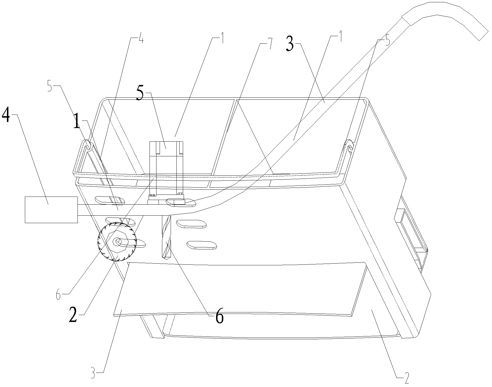
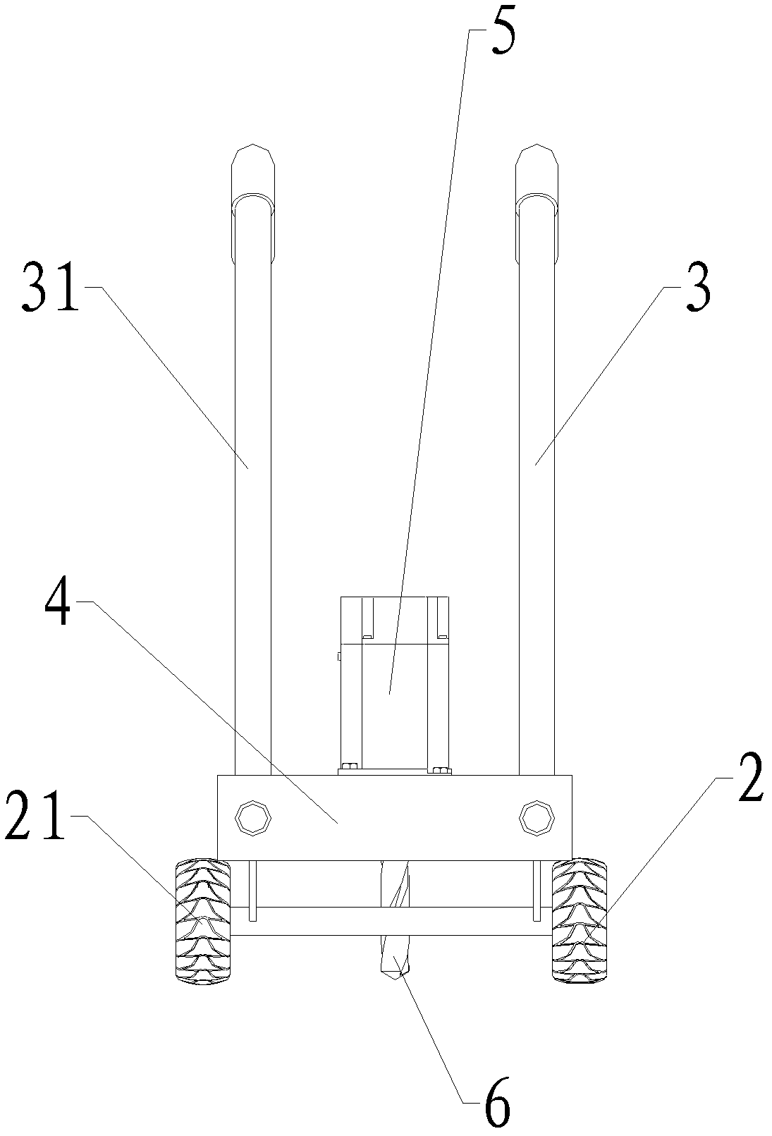
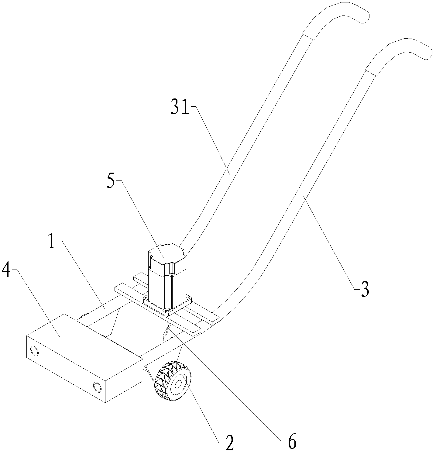
[0014] Examples such as figure 1 , figure 2 , image 3 As shown, the electric pipe hole chamfering trolley includes a car body platform 1, the bottom of the car body platform 1 is provided with wheels 2 and wheels 21, the rear of the car body platform 1 is provided with handrails 3 and 31, and the wheels 2 and 21 The car body platform 1 in the place ahead of the rotating shaft is provided with counterweight 4, and the car body platform 1 at the rear of the wheel 2 and the wheel 21 rotating shaft is provided with a motor 5, and the rotating shaft of the motor 5 is provided with a drill bit 6, and the drill bit 6 is connected to the car body. The platform 1 is vertical and arranged downwards, the rotating shaft of the motor 5 is provided with a drill bit 6, and the ends of the handrail 3 and the handrail 31 are respectively provided with a curved handle, the diameter of the curved handle is 30 cm, and the motor 5 drives the drill bit to rotate when it rotates. Complete the ch...


PUM


Abstract

The invention relates to an electric pipe hole chamfering trolley, which comprises a trolley body platform. Wheels are arranged at the bottom of the trolley body platform, two armrests are arranged in the rear of the trolley body platform, a counterweight block is arranged in the front of a wheel rotating shaft on the trolley body platform, a motor is arranged at the back of the wheel rotating shaft on the trolley body platform, a drill bit perpendicular to the trolley body platform is downwardly arranged on a rotary shaft of the motor, and bent handles are arranged at ends of the two armrests respectively. An operator can hold the bent handles with hands to control the drill bit to rapidly chamfer pipe holes on a pipe sheet and a baffle with large diameters, and the electric pipe hole chamfering trolley is convenient and flexible in application. Holding time of large equipment can be shortened, so that profitability in unit time is improved for enterprises. The counterweight block and the motor are arranged in the front and at the back of the wheel rotating shaft respectively, the labor intensity of operators is reduced, operation is facilitated, production cost can be reduced, and the production cycle of products is greatly shortened.

Description

technical field [0001] The invention relates to a tube hole chamfering device, in particular to an electric tube hole chamfering trolley suitable for chamfering the tube holes of a heat exchanger tube plate and a baffle, and belongs to the field of mechanical technology. Background technique [0002] At present, when the tube holes of the tube sheet and baffle of the traditional heat exchanger are chamfered, the radial drill is usually used for positioning chamfering. Because the radial drill has the defect of inflexibility in operation, the tube sheet and baffle When the diameter is relatively large, only a large radial drilling machine can be used for chamfering, which is inconvenient to operate; when the output of the heat exchanger is relatively high, it will bring about a large workload and low work efficiency, resulting in high production costs. Contents of the invention [0003] The problem to be solved by the present invention is to provide an electric tube hole ch...

Claims


Application Information

Patent Timeline
IPC IPC(8): B23B45/14
Inventor 于普明刘锡荣李松明于才恒
Owner QINGDAO JIENENG HIGH&NEW TECH
Why Eureka
Try Eureka