Weld line pressure plate

A pressing plate and welding wire technology, which is applied in the direction of welding equipment, welding equipment, non-electric welding equipment, etc., can solve the problems of easy deformation of PCB board, unsatisfactory welding effect, contact with the bottom surface of the pressing plate, etc., so that it is not easy to release and avoid bad welding wire , the effect of gathering and heating up quickly

Active Publication Date: 2014-04-30
GOERTEK MICROELECTRONICS CO LTD
View PDF8 Cites 0 Cited by
  • Summary
  • Abstract
  • Description
  • Claims
  • Application Information

AI Technical Summary

Problems solved by technology

[0003] The existing welding wire pressing plate has a large welding wire window in the welding area. During the wire welding process, the PCB board in the window is easily deformed and appears suspended, causing part of the ultrasonic energy to be released, and the welding effect is not ideal; now The bottom surface of some welding wire pressing plates is a smooth plane. When the welded product is deformed, the product contacts the bottom surface of the pressing plate, resulting in poor welding wires.

Method used


Image

  • Weld line pressure plate
  • Weld line pressure plate
  • Weld line pressure plate

Examples


Embodiment Construction

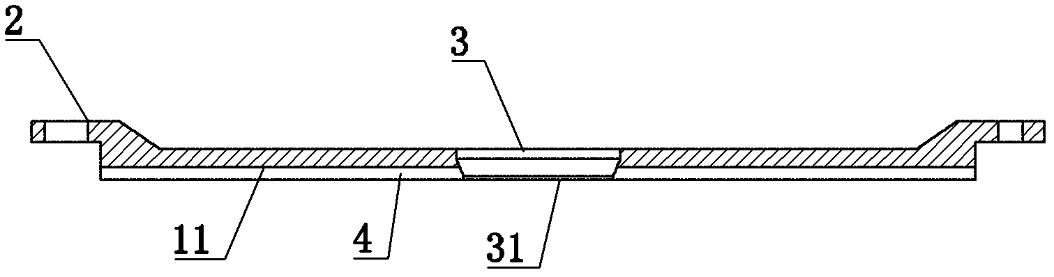
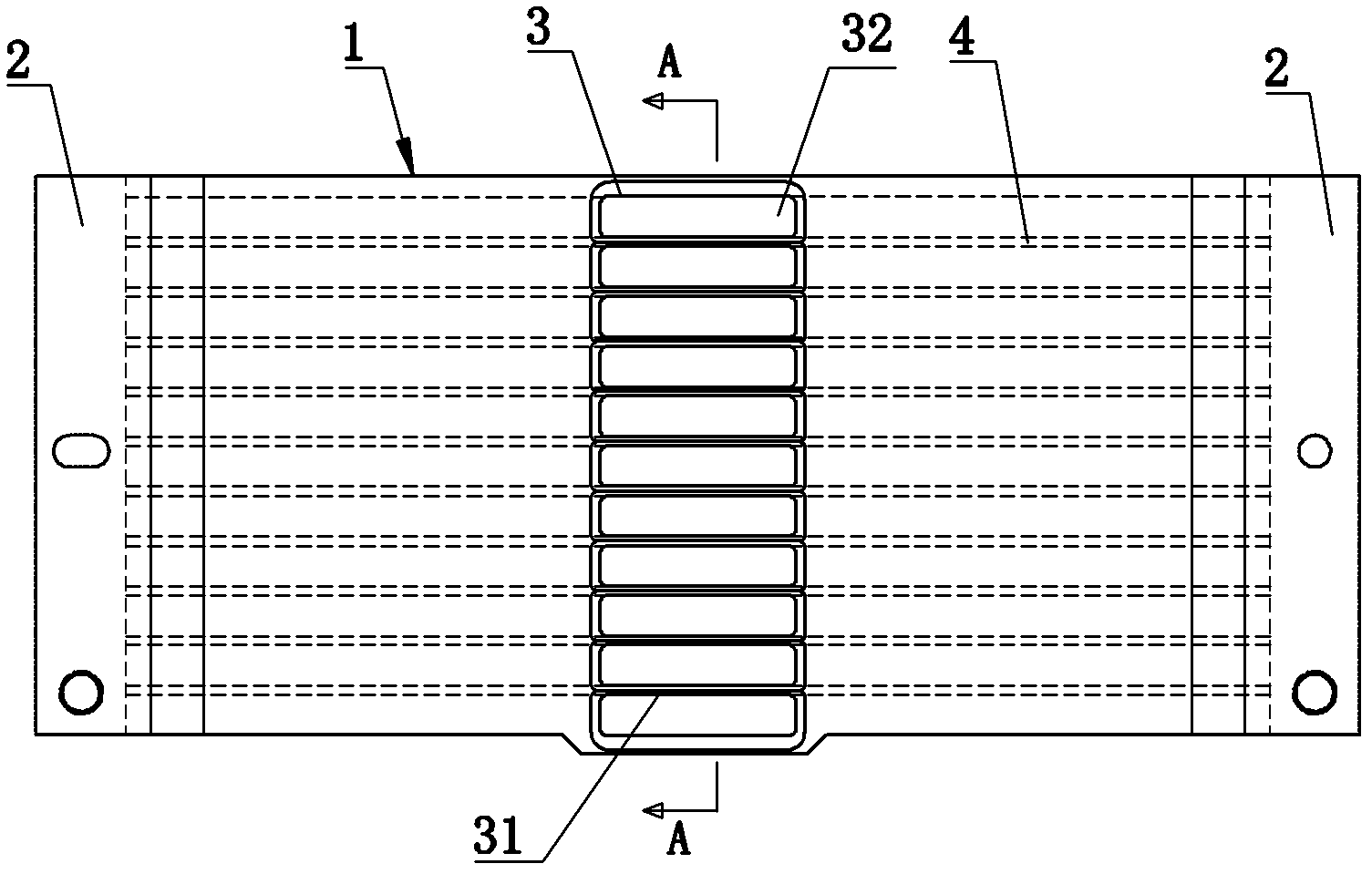
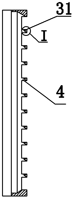
[0015] Such as figure 1 , figure 2 with image 3 Commonly shown, the welding wire pressing plate includes a pressing plate body 1, the bottom of the pressing plate body 1 is a pressing material surface 11, and the two sides of the pressing plate body 1 are respectively provided with installation parts 2 for connecting with the machine. Wire window 3, the welding wire window 3 is provided with several slitting ribs 31 arranged in parallel, and the slitting ribs 31 separate the welding wire window 3 into several welding areas 32, and the slitting ribs 31 are along the surface of the binder surface 11 toward Both sides extend and form ribs 4 protruding from the binder surface 11 , and two adjacent ribs 4 and the binder surface 11 jointly enclose an accommodating area.

[0016] Since there are several undivided small PCB boards neatly arranged on the overall PCB board, there are gaps between these small PCB boards. In the gaps between these undivided small PCB boards, the comp...


PUM


Abstract

The invention discloses a weld line pressure plate, which comprises a pressure plate body. The bottom of the pressure plate body is a material pressing surface, mounting portions used for being connected with a cabinet are disposed on two sides of the pressure plate body respectively, a weld line window is arranged on the pressure plate body, a plurality of slitting ribs are parallelly disposed on the weld line window and divide the weld line window into a plurality of welding areas, the slitting ribs extends along the surface of the material pressing surface to two sides of the material pressing surface and form convex ribs protruded on the material pressing surface, and each two adjacent convex ribs and the material pressing surface jointly encircle to form a holding area. The welding window is divided into the welding areas by the slitting ribs, acoustic resistance is high when ultrasonic welding is carried out in relatively small areas, ultrasonic energy is quickly gathered for heating and cannot be released easily, and accordingly ultrasonic welding quality is improved. In addition, due to the convex ribs, each welding elements is positioned in the corresponding holding area jointly encircled by the corresponding two convex ribs and the material pressing surface, the welding elements cannot be damaged easily, and the weld line pressure plate brings convenience for welding and prevents defective weld lines.

Description

technical field [0001] The invention relates to a welding wire fixture, in particular to a welding wire pressing plate. Background technique [0002] The welding wire pressing plate is mainly used for fixing and leveling the PCB board during wire welding, so as to ensure that the PCB board is under stress during wire welding, so that the effect of ultrasonic waves can be released more completely. [0003] The existing welding wire pressing plate has a large welding wire window in the welding area. During the wire welding process, the PCB board in the window is easily deformed and appears suspended, causing part of the ultrasonic energy to be released, and the welding effect is not ideal; now The bottom surface of some welding wire pressing plate is a smooth plane, and the phenomenon that the product contacts the bottom surface of the pressing plate when the welded product is deformed causes the welding wire to be defective. Therefore, the wire bonding plate needs to be impr...

Claims


Application Information

Patent Timeline
Patent Type & Authority Patents(China)
IPC IPC(8): B23K37/04B23K20/10
Inventor 孙德波徐霞李宁波
Owner GOERTEK MICROELECTRONICS CO LTD
Why Eureka
Try Eureka