Double-heat-energy warming fermentation tank

A fermenter and thermal energy technology, applied in the field of fermenter, can solve the problems of poor warming effect, unsuitable for large-scale biogas projects, etc., and achieve the effect of not easy to lose, good warming effect, and good warming effect

Active Publication Date: 2012-07-18
方朝阳
View PDF7 Cites 2 Cited by
  • Summary
  • Abstract
  • Description
  • Claims
  • Application Information

AI Technical Summary

Problems solved by technology

[0007] The purpose of the present invention is to overcome the defects and problems existing in the prior art that the warming effect is poor and not suitable for large-scale biogas projects, and to provide a dual-heat heating type fermentation with good warming effect and suitable for large-scale biogas projects Can

Method used


Image

  • Double-heat-energy warming fermentation tank
  • Double-heat-energy warming fermentation tank
  • Double-heat-energy warming fermentation tank

Examples


Embodiment 1

[0067] Example 1: The No. 1 solar heating room and biomass heating room are suitable for the production of straw biogas or mixed biogas of straw and feces.

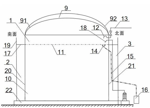
[0068] see figure 2 and image 3 , a kind of double heat energy heating type fermenter, comprises fermenter 1, No. 1 solar energy warming room 4 and biological energy warming room 5, and described fermenter 1 comprises tank body 10 and the gas film 9 that top is provided with, and gas The membrane 9 includes an inner membrane 91 and an outer membrane 92. The inside of the air membrane 9 communicates with the air duct. On the side wall of the tank body 10, the position between the inner membrane 91 and the discharge height line 11 of the liquid level is provided with an air outlet 12 and a flushing hole. Shower head 18, an overflow port 14 is set below the liquid surface discharge height line 11, the gas outlet 12 communicates with the biogas pipe 13, the shower head 18 corresponds to the overflow port 14, and the overfl...

Embodiment 2

[0072] Example 2: No. 2 solar warming room and fully enclosed boiler direct heating room are suitable for the production of feces biogas.

[0073] see Figure 4 – Image 6 , the basic content is the same as in Example 1, the difference is that:

[0074] A double heat energy heating fermenter, including fermenter 1, No. 2 solar warming room 6 and fully enclosed boiler direct heating room 7, No. 2 solar warming room 6 and fully enclosed boiler direct heating Room 7 is connected;

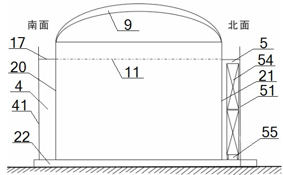
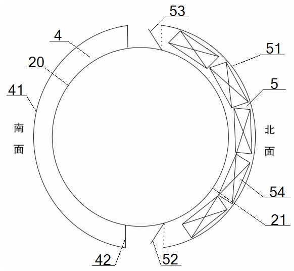
[0075] The No. 2 solar warming room 6 includes an arc-shaped transparent glass wall 41 and a closed door 42. The transparent glass wall 41 is arranged around the south side wall 20. The two ends of the transparent glass wall 41 are respectively connected to the closed door 42 and the No. The walls 71 are connected, and the top of the transparent glass wall 41 is provided with a platform 17;

[0076] The fully enclosed boiler direct heating type warming room 7 includes arc-shaped No. 2 thermal insul...


PUM

PropertyMeasurementUnit
widthaaaaaaaaaa
widthaaaaaaaaaa
widthaaaaaaaaaa

Abstract

The invention provides a double-heat-energy warming fermentation tank. The double-heat-energy warming fermentation tank comprises a fermentation tank, a solar warming device and an auxiliary heat energy warming device, wherein the solar warming device is arranged around the south side wall of the tank body; the auxiliary heat energy warming device is arranged around the north side wall of the tank body; platforms are arranged at the tops of both the auxiliary heat energy warming device and the solar warming device; the solar warming device, the auxiliary heat energy warming device, the platforms, the ground and the black tank body side walls mutually form a sealed structure; the auxiliary heat energy warming device is a biological energy warming room or a full-sealed boiler directly-heated type warming room; straw fermentation warming is adopted for the biological energy warming room; and the full-sealed safety and energy-saving biogas boiler near-fermentation warming is adopted for the full-sealed boiler directly-heated type warming room. The double-heat-energy warming fermentation tank provided by the invention has the advantages of good warming effect, stronger energy conservation, low cost, strong environment friendliness and suitability for large-sized biogas projects.

Description

technical field [0001] The invention relates to a fermenter, in particular to a dual heat energy temperature-increasing fermenter, which is particularly suitable for the heat preservation process of the fermenter in biogas engineering. Background technique [0002] At present, the insulation process of fermentation tanks in traditional large-scale biogas projects is to wrap a layer of insulation cotton on the surface of the tank body. The biggest disadvantage of this insulation mode is that it rejects the entry of solar energy while maintaining insulation, and its insulation effect is poor. It can only ensure that the temperature of the tank is 10-20°C, which affects the fermentation temperature in the fermentation tank, which not only causes the fermentation material to decompose and digest for a long time, but also leads to an increase in the height of the tank, which increases the production cost and reduces the gas production rate. , resulting in a gas production rate of...

Claims


Application Information

Patent Timeline
Patent Type & Authority Applications(China)
IPC IPC(8): C12M1/107
CPCY02E50/343C12M41/12C12M43/00C12M21/04Y02E50/30
Inventor 方朝阳
Owner 方朝阳
Why Eureka
Try Eureka