Completely recyclable end support ground anchor
A ground anchor and end bearing technology, used in construction, sheet pile wall, infrastructure engineering and other directions, can solve the problems of unrecoverable components, complicated recovery operations, and low bearing capacity, and achieve cost savings, clean and fast disassembly, and anchorage. powerful effect
- Summary
- Abstract
- Description
- Claims
- Application Information
AI Technical Summary
Problems solved by technology
Method used
Image
Examples
Embodiment 1
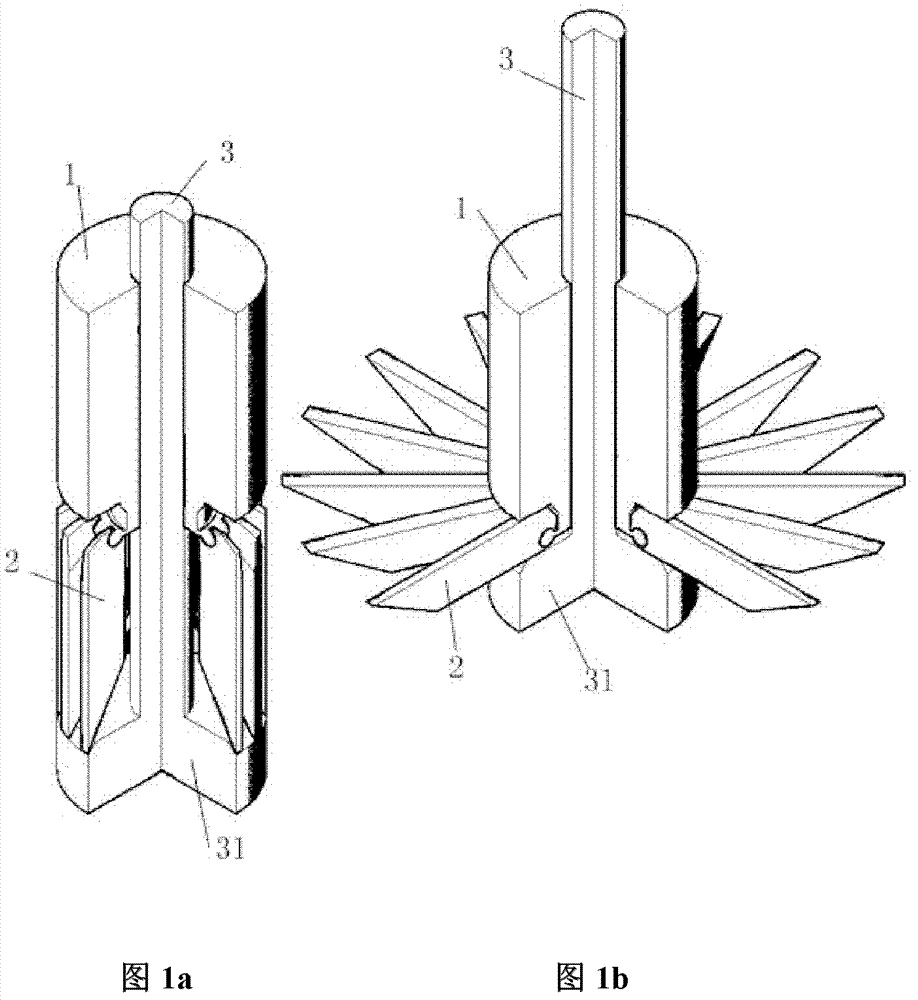
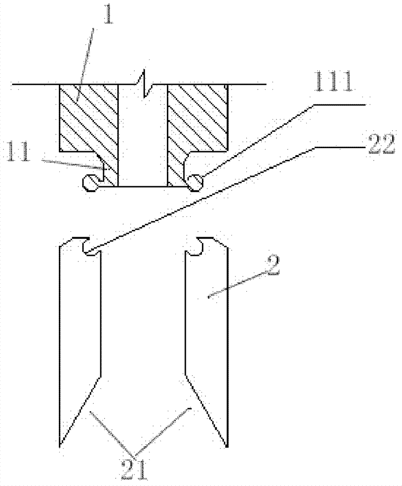
[0048] Figure 1 is a perspective view of Embodiment 1 of the fully recoverable end-support ground anchor of the present invention. For ease of observation, a part is cut along the axis of the anchor sleeve 1 in the figure. As shown in Figure 1, the end support of the present invention The ground anchor includes an anchor sleeve 1, an anchor claw 2, and an anchor rod 3. The anchor rod 3 is a straight rod with a disc-shaped flange 31 at the lower end. The anchor rod 3 is covered with a tubular anchor sleeve 1, and the bottom surface of the anchor sleeve 1 is An annular protrusion 11 is provided. As shown in FIG. 2 , there are multiple anchor flukes 2 , and the upper end of each anchor fluke 2 is hinged on the outer edge of the lower end of the annular protrusion 11 on the bottom surface of the anchor rod sleeve 1 .
[0049] Figure 2a It is the structure in which the upper end of each anchor fluke is hinged on the outer edge of the lower end of the annular protrusion on the bott...
Embodiment 2
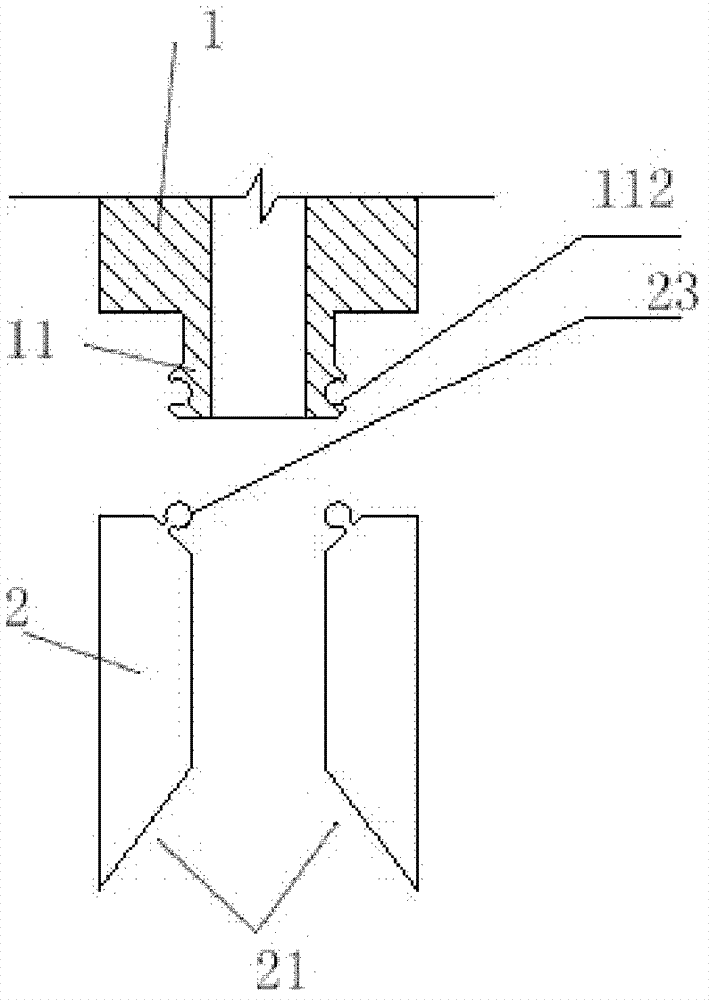
[0057] Such as Figure 2b , 3b , 4b, 7a, and 7b are the corresponding views of the second embodiment of the present invention. The difference between the second embodiment and the first embodiment is that the upper end of each anchor fluke in the second embodiment is hinged on the outer edge of the lower end of the annular protrusion on the bottom surface of the anchor sleeve. The outer edge of the lower end is provided with an annular inner groove 112, and the upper end of the fluke 2 is provided with an outer convex edge 23 embedded in the annular inner groove 112 to form a hinged relationship.
[0058] The specific construction process of the second embodiment is the same as that of the first embodiment.
Embodiment 3
[0060] Fig. 8 and Fig. 9 are respectively the state diagrams when the fluke 2 is folded and when the fluke 2 is unfolded according to the third embodiment of the present invention, the difference from the first embodiment is:
[0061] The upper end of the anchor rod 3 is provided with an external thread, and the lifting end nut 4 is arranged on the anchor rod sleeve 1 , and the anchor rod 3 is installed on the anchor rod sleeve 1 through the lifting end nut 4 . The lifting end nut 4 is arranged on the upper end surface of the anchor rod sleeve 1. At this time, the lifting end nut 4 is only in contact with the anchor rod sleeve 1. Rotate the lifting end nut 4 upward or downward to lift or loosen the anchor rod 3. Realize the expansion or retraction of anchor fluke 2. The lifting end nut 4 can also be fixedly arranged in the lumen of the anchor rod sleeve 1 or the upper and lower ends of the anchor rod sleeve 1, such as being fixed at the lower end of the anchor rod sleeve 1. At...
PUM
 Abstract
Description
Claims
Application Information
 - R&D
- Intellectual Property
- Life Sciences
- Materials
- Tech Scout
- Unparalleled Data Quality
- Higher Quality Content
- 60% Fewer Hallucinations
Browse by: Latest US Patents, China's latest patents, Technical Efficacy Thesaurus, Application Domain, Technology Topic, Popular Technical Reports.
© 2025 PatSnap. All rights reserved.Legal|Privacy policy|Modern Slavery Act Transparency Statement|Sitemap|About US| Contact US: help@patsnap.com


