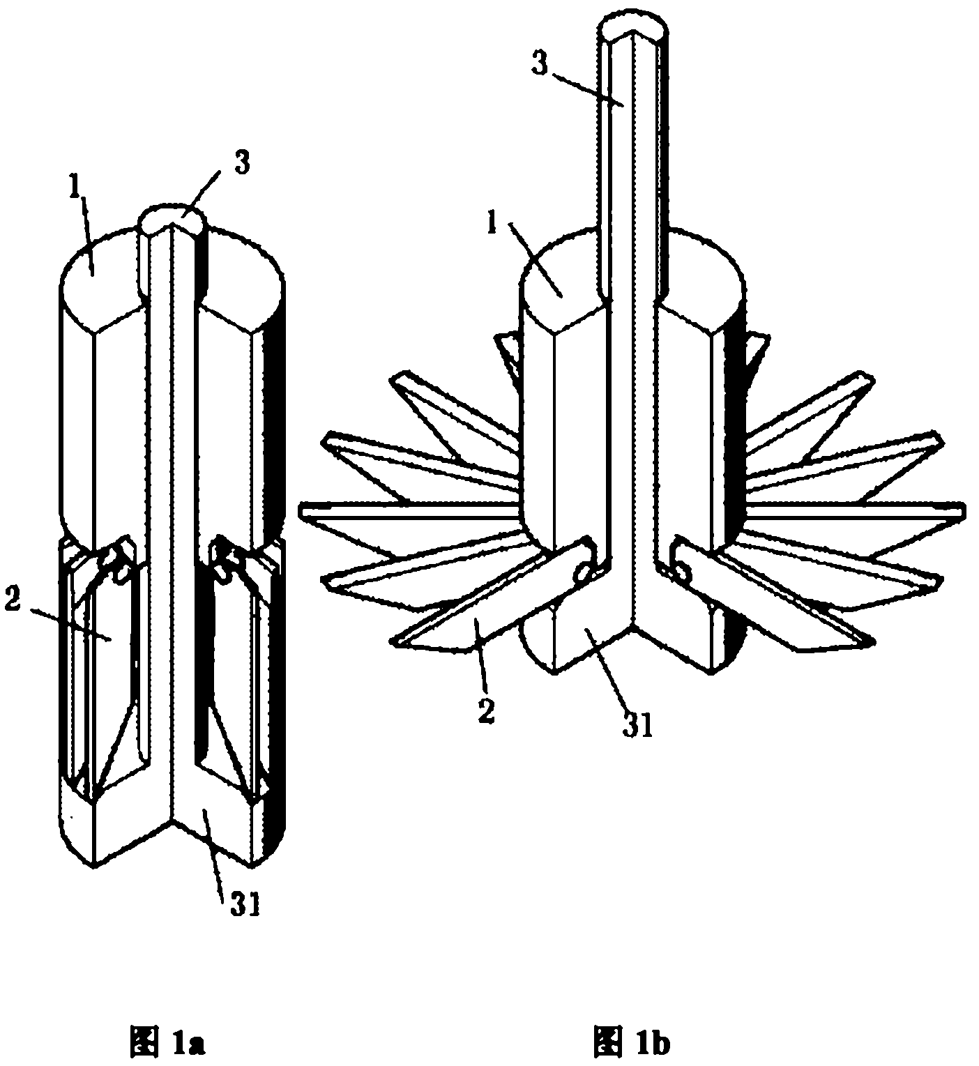
Completely recyclable end support ground anchor

A ground anchor and end bearing technology, applied in construction, sheet pile wall, infrastructure engineering, etc., can solve the problems of non-recyclable components, complicated recycling operations, low bearing capacity, etc., to achieve cost saving, clean and fast disassembly, and anchor powerful effect

Active Publication Date: 2012-07-18
覃永忠
View PDF8 Cites 19 Cited by
  • Summary
  • Abstract
  • Description
  • Claims
  • Application Information

AI Technical Summary

Problems solved by technology

"Combined with the structure of its small number of anchor claws, it can be known that the bearing capacity of this type of anchor is not large. This kind of ground anchor has one of the biggest shortcomings: "The anchor head and anchor rod of this umbrella anchor can be separated, and the anchor rod can be reassembled. "Using" indicates that the structure can only take out the anchor rod, but not the anchor head and anchor rod cover (umbrella strands, tensile flexible nets and anchor edges, etc.), most of the components cannot be recycled, and there is a lot of waste
[0007] The application number is 200720069921.9, the announcement number is CN201031390Y, and the Chinese utility model patent titled "tool-type enlarged head uplift pile". into the soft soil or sandy soil, and then driven by the jack to open the fins at the bottom of the pile to generate pull-out resistance, and because of the large space between the opened fins during recovery, the soft soil is easy to enter the above space, so it is also It takes a lot of force to recover
[0008] Therefore, although this utility model can provide a large anchoring force and can also be recovered, the required equipment is large and the recovery operation is also complicated

Method used


Image

  • Completely recyclable end support ground anchor
  • Completely recyclable end support ground anchor
  • Completely recyclable end support ground anchor

Examples


Embodiment 1

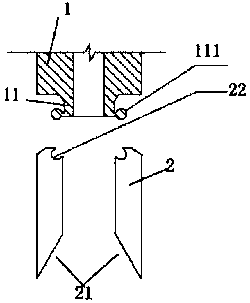
[0048] Figure 1 is a perspective view of Embodiment 1 of the fully recoverable end-support ground anchor of the present invention. For ease of observation, a part is cut along the axis of the anchor sleeve 1 in the figure. As shown in Figure 1, the end support of the present invention The ground anchor includes an anchor sleeve 1, an anchor claw 2, and an anchor rod 3. The anchor rod 3 is a straight rod with a disc-shaped flange 31 at the lower end. The anchor rod 3 is covered with a tubular anchor sleeve 1, and the bottom surface of the anchor sleeve 1 is An annular protrusion 11 is provided. As shown in FIG. 2 , there are multiple anchor flukes 2 , and the upper end of each anchor fluke 2 is hinged on the outer edge of the lower end of the annular protrusion 11 on the bottom surface of the anchor rod sleeve 1 .

[0049] Figure 2a It is the structure in which the upper end of each anchor fluke is hinged on the outer edge of the lower end of the annular protrusion on the bott...

Embodiment 2

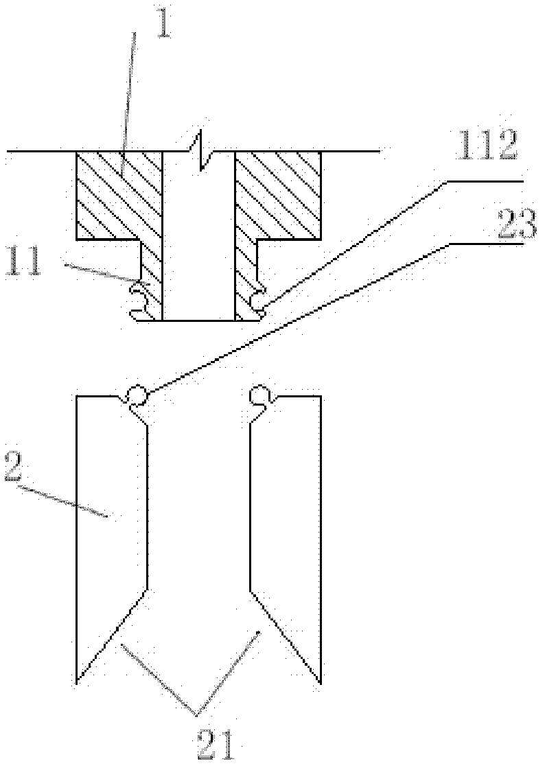
[0057] Such as Figure 2b , 3b , 4b, 7a, and 7b are the corresponding views of the second embodiment of the present invention. The difference between the second embodiment and the first embodiment is that the upper end of each anchor fluke in the second embodiment is hinged on the outer edge of the lower end of the annular protrusion on the bottom surface of the anchor sleeve. The outer edge of the lower end is provided with an annular inner groove 112, and the upper end of the fluke 2 is provided with an outer convex edge 23 embedded in the annular inner groove 112 to form a hinged relationship.

[0058] The specific construction process of the second embodiment is the same as that of the first embodiment.

Embodiment 3

[0060] Fig. 8 and Fig. 9 are respectively the state diagrams when the fluke 2 is folded and when the fluke 2 is unfolded according to the third embodiment of the present invention, the difference from the first embodiment is:

[0061] The upper end of the anchor rod 3 is provided with an external thread, and the lifting end nut 4 is arranged on the anchor rod sleeve 1 , and the anchor rod 3 is installed on the anchor rod sleeve 1 through the lifting end nut 4 . The lifting end nut 4 is arranged on the upper end surface of the anchor rod sleeve 1. At this time, the lifting end nut 4 is only in contact with the anchor rod sleeve 1. Rotate the lifting end nut 4 upward or downward to lift or loosen the anchor rod 3. Realize the expansion or retraction of anchor fluke 2. The lifting end nut 4 can also be fixedly arranged in the lumen of the anchor rod sleeve 1 or the upper and lower ends of the anchor rod sleeve 1, such as being fixed at the lower end of the anchor rod sleeve 1. At...


PUM


Abstract

The invention discloses a completely recyclable end support ground anchor, which comprises an anchor rod, an anchor rod sleeve and anchor flukes. The anchor rod is a straight rod with the lower end provided with disc-shaped flanges; the tubular anchor rod sleeve is sheathed on the lower part of the anchor rod; circular flanges are arranged on the bottom surface of the anchor rod sleeve; and upper ends of a plurality of anchor flukes are hinged on the outer edges at the lower ends of the circular flanges arranged on the bottom surface of the anchor rod sleeve. According to the invention, the end support ground anchor can be put into use immediately after being assembled and has a plurality of anchor flukes and large anchoring force, the assembly and the disassembly is fast and convenient, and the complete recycling of the ground anchor is not influenced even if collapse happens to the bottom of an anchor hole.

Description

technical field [0001] The present invention mainly relates to the field of rock-soil anchorage in construction engineering, and in particular to a temporary and fully recyclable end-bearing ground anchor. Anti-force anchoring system for static load tests on foundations, etc. Background technique [0002] At present, the bolt technology used in engineering is mostly fixed and non-removable bolts, and there are also a few removable bolts. There are some bolts that are anchored into the soil, but this type of bolt has few claws and small anchoring force, and because the claws are anchored into the soil, it is difficult to remove them. It can be known from the mechanical properties of rock and soil that the end bearing capacity of various rock and soil is much greater than the friction provided by it. Just because the side friction force provided by the geotechnical system is small, if a larger anchoring force is required, only by increasing the diameter, length and quant...

Claims


Application Information

Patent Timeline
Patent Type & Authority Applications(China)
IPC IPC(8): E02D5/80
Inventor 覃永忠
Owner 覃永忠
Why Eureka
Try Eureka