
Web beam, preparation method thereof, and overhead structure used for CSI dwelling house and formed by web beam

A web and plate beam technology, applied in the field of CSI residential overhead structure, can solve the problems of not considering pipeline layout, high engineering cost, and large amount of steel, and achieve the effects of material saving, convenient construction and good mechanical performance.

Inactive Publication Date: 2012-07-18
王全良 +1
View PDF5 Cites 2 Cited by
  • Summary
  • Abstract
  • Description
  • Claims
  • Application Information

AI Technical Summary

Problems solved by technology

[0003] One of the purposes of the present invention is to solve the problems of high steel consumption and high engineering cost in the prior art, and the problem of pipeline layout is not considered, and then provides a web beam

Method used


Image

  • Web beam, preparation method thereof, and overhead structure used for CSI dwelling house and formed by web beam
  • Web beam, preparation method thereof, and overhead structure used for CSI dwelling house and formed by web beam
  • Web beam, preparation method thereof, and overhead structure used for CSI dwelling house and formed by web beam

Examples


Embodiment 1

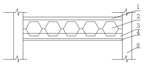
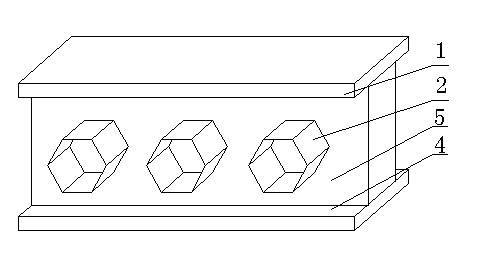
[0032] Reference attached figure 1 , 2 , a web beam, comprising an upper flange plate 1, a lower flange plate 4 and a web 5, the upper flange plate 1 is affixed to the upper end surface of the web plate 5, and the lower wing is affixed to the lower end surface of the web plate 5 The edge plate 4 and the web plate 5 are uniformly or unevenly provided with a plurality of threading holes 2 along the length direction.

[0033] In practice, considering the convenience of processing and material saving, the web is divided into an upper web 5-1 and a lower web 5-2, the upper web 5-1 is provided with upper teeth a, and the corresponding position of the lower web 5-2 is provided with The lower teeth b, upper teeth a and lower teeth b are fixed to form threading holes 2, and the shape and size of each threading hole 2 formed after the upper teeth a of the upper web 5-1 and the lower teeth b of the lower web 5-2 are fixed Similarly, the threading holes 2 formed after the upper teeth a ...

Embodiment 2

[0038] combined with Figure 6 , 7 Describe this embodiment. The difference between this embodiment and Embodiment 1 is that the threading hole 2 is circular. Reference attached Figure 8 , the preparation method of the web beam described in this embodiment, the tooth-shaped cutting line 6 is arc-shaped. Other compositions and connections and preparation steps are the same as in Example 1.


PUM


Abstract

The invention relates to a web beam, a preparation method thereof, and an overhead structure used for a CSI dwelling house and formed the web beam. The web beam comprises au upper flange plate, a lower flange plate and a web, and a plurality of threading holes are uniformly or nonuniformly arranged on the web along the length direction. The preparation method of the web beam comprises the following steps: determining the threading holes, uniformly or nonuniformly, periodically and repeatedly marking a tooth-shaped cutting line along the length direction of the web body, cutting along the tooth-shaped cutting line to obtain an upper web and a lower web, offsetting the obtained groove part, welding upper teeth and lower teeth to form the web, and welding the upper flange plate and the lower flange plate. The overhead structure for the CSI dwelling house comprises two wallboards, a lower flour, an overhead floor and the web beam, the upper flange plate and the overhead floor are in the same plane, the lower flange plate and the lower flour are in the same plane, an upper flour space is above the upper flange plate and the overhead floor, and a lower flour space without a beam is under the lower flange plate.

Description

technical field [0001] The invention relates to the technical field of building steel structures, in particular to a web girder, a preparation method and a CSI residential overhead structure composed of the same. Background technique [0002] At present, the steel structure system has gradually become the first choice in the construction field due to its advantages of economy and speed. The more commonly used ones are hot-rolled I-beams, hot-rolled H-beams and welded H-beams. The steel components used in the existing steel structure have the problems of high steel consumption and high engineering cost. In addition, the problem of pipeline layout is not considered in terms of use. Contents of the invention [0003] One of the objectives of the present invention is to provide a web girder to solve the problems of high steel consumption and high engineering cost in the prior art, without considering the pipeline layout. [0004] In order to achieve the above object, the tech...

Claims


Application Information

Patent Timeline
Patent Type & Authority Applications(China)
IPC IPC(8): E04C3/08E04G21/00E04B1/24
CPCE04C3/086
Inventor 王全良张波
Owner 王全良
Learn More