Shellless fracturing bomb and burning speed control method thereof

A fracturing bomb and pressure relief technology, which is used in earth-moving drilling, production of fluids, wellbore/well components, etc., can solve problems such as the inability to meet pressure loading, and achieve the goal of increasing the single-well charge, improving the effect, and prolonging the pressure. effect of action time

Active Publication Date: 2012-07-18
GANSU RES INSTION OF CHEM IND GRICI +1
View PDF5 Cites 0 Cited by
  • Summary
  • Abstract
  • Description
  • Claims
  • Application Information

AI Technical Summary

Problems solved by technology

[0007] Another object of the present invention is to provide a method for controlling the burning rate of caseless fracturing bombs, so as to so

Method used


Image

  • Shellless fracturing bomb and burning speed control method thereof
  • Shellless fracturing bomb and burning speed control method thereof
  • Shellless fracturing bomb and burning speed control method thereof

Examples


Embodiment approach

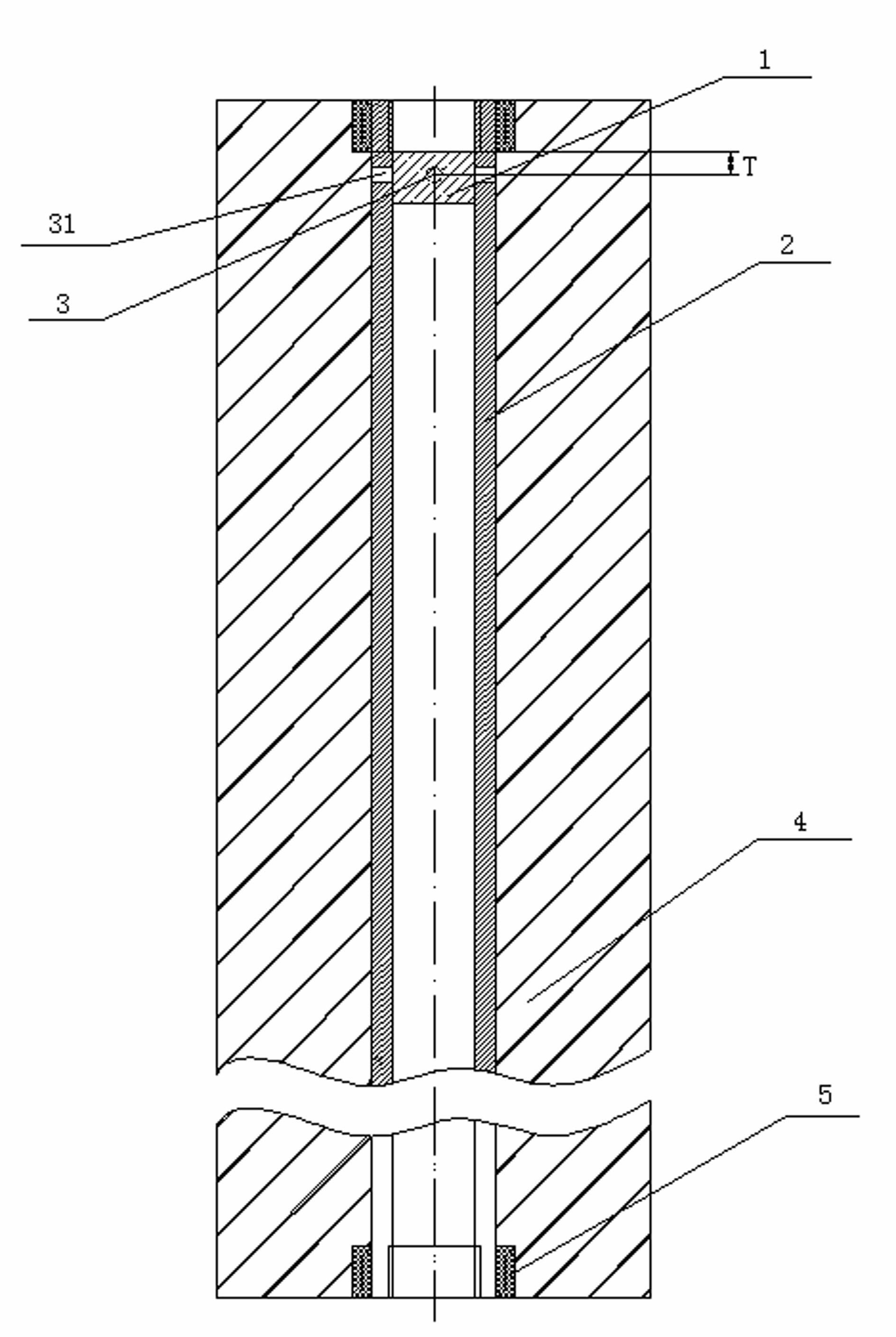
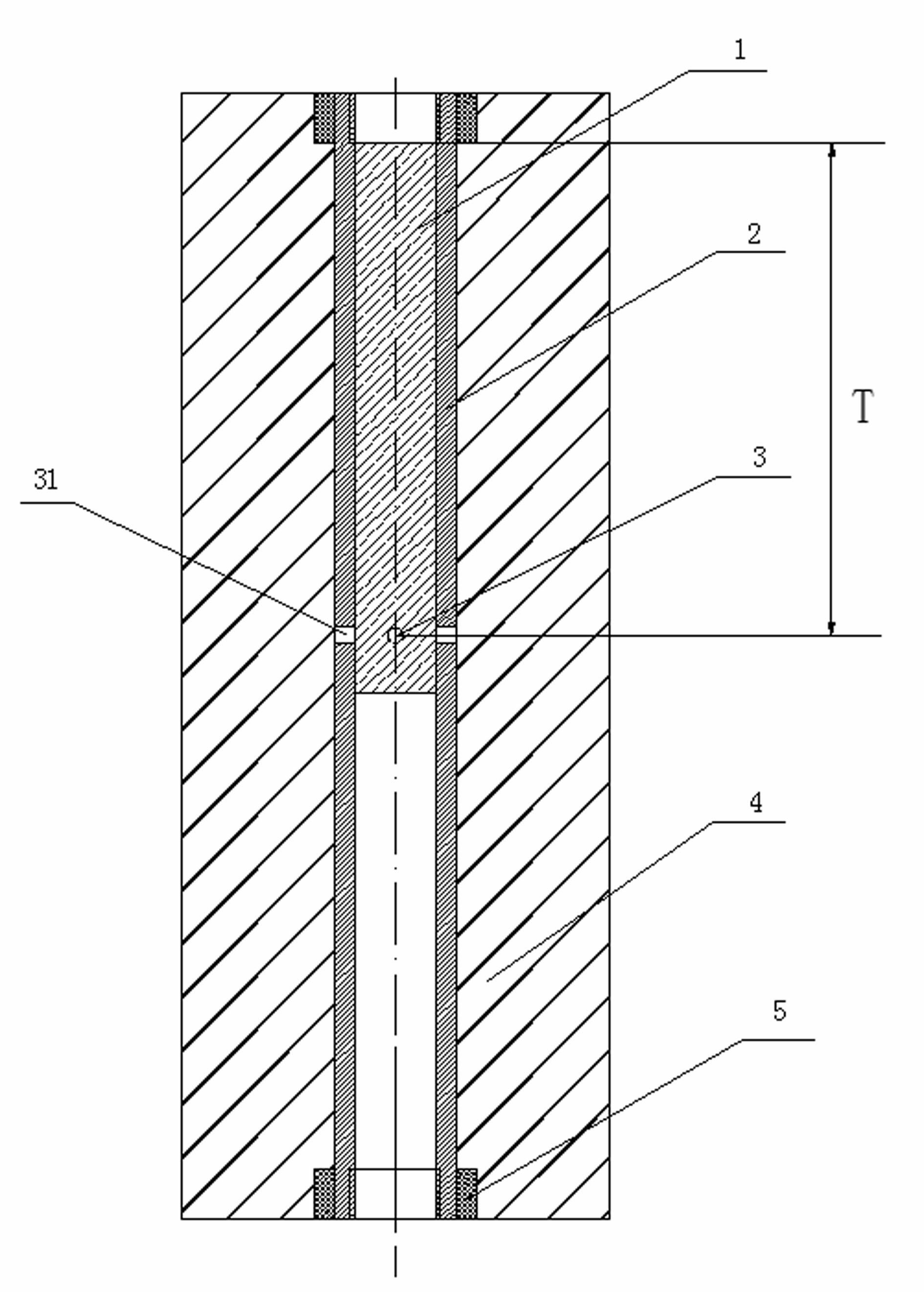
[0028] figure 1 The first embodiment of the present invention is shown, the side wall of the central tube 2 is provided with a group of ignition holes 31, and the group of ignition holes 31 are located at one end of the central tube 2, and are ignited by the ignition device, and the ignition holes inside the central tube 2 are first ignited. The gunpowder 1 ignites the gunpowder column 4 through the ignition hole 31 on the side wall of the central tube 2 . In this case, since the propellant at one end of the propellant column 4 is ignited first, the propellant column 4 is similar to burning at the end face, which is the slowest burning rate of the caseless fracturing bomb.

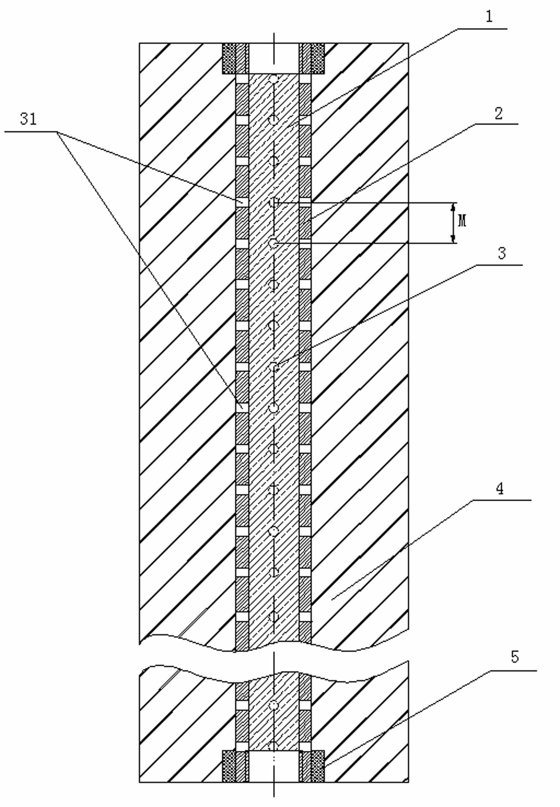
[0029] figure 2 Shows the second embodiment of the present invention, the side wall of the central tube 2 is provided with a group of ignition holes 31, the group of ignition holes 31 are located in the middle of the central tube 2, the ignition device does not illustrate the ignition, and ignites the gu...

Embodiment 1

[0038] The caseless fracturing bomb includes two groups of ignition holes 31. When the two groups of ignition holes 31 are located at one end of the central tube 2, the distance M between the two groups of ignition holes 31 is equal to 5 mm, and the group of ignition holes at the end The distance T from the near-end pressure relief part 5 of the central tube 2 is equal to the distance from the ignition hole, the burning time of the caseless fracturing bomb is 114.31s, and the burning rate is 0.06kg / s.

Embodiment 2

[0040] The caseless fracturing bomb includes two sets of ignition holes 31, which are located in the axial direction of the central tube 2 and distributed evenly, and the distance between the two sets of ignition holes 31 is the set of ignition holes at the end to the central tube 2 When the distance of the proximal pressure relief part 5 is twice the distance, the burning time of the caseless fracturing bomb is 26.31s, and the burning rate is 0.25kg / s; when the positions of the two sets of ignition holes 31 are along the axial direction of the central tube When changing, the burning rate of the caseless fracturing bomb varies between 0.06kg / s -0.25kg / s.


PUM


Abstract

The invention discloses a shellless fracturing bomb and a burning speed control method thereof, which solve the problem that the existing shellless fracturing bomb cannot satisfy pressure loading matched with oil well oil layer characteristics. The shellless fracturing bomb comprises ignition powder, a central tube, a powder column and pressure relief portions. The pressure relief portions symmetrically arranged at two ends of the powder column, the side wall of the central tube is provided with at least one group of ignition holes, and each group of ignition holes includes three to six ignition holes is positioned on a same plane axially perpendicular to the central tube. The burning speed control method of the shellless fracturing bomb includes steps: determining group amount of the ignition holes according to required burning speed of the shellless fracturing bomb, and arranging the position of each group of ignition holes on the side wall of the central tube according to the group amount of the ignition holes. Pressure loading conditions under different well conditions and geological conditions can be met, fracturing production increasing and injection increasing effect can be improved, and protection of an oil well shaft can be benefited.

Description

technical field [0001] The invention relates to a method for increasing production and injection of an oil-water well in an oil field, in particular to a caseless fracturing bomb and a method for controlling the burning rate of the caseless fracturing bomb. Background technique [0002] High-energy gas fracturing is to use energy gunpowder to burn in the wellbore of the oil well, and the high-temperature and high-pressure gas generated acts on the target oil layer to form multiple radial fractures that are not affected by in-situ stress, effectively improving the seepage environment of the oil layer near the wellbore, and achieving oil and gas well stimulation. , The purpose of increasing the injection of water injection wells. High-energy gas fracturing can be used for oil well reservoir reconstruction, improve oil layer permeability, and increase oil well production; it can also be used to increase oil layer water absorption capacity, improve water absorption profile, expa...

Claims


Application Information

Patent Timeline
IPC IPC(8): E21B43/263
Inventor 傅仁军耿俊杰刘春峰潘祖跃李建科司洛霖张彤马宝成高洁陈东明
Owner GANSU RES INSTION OF CHEM IND GRICI
Why Eureka
Try Eureka