
Lifting mechanism for fans

A lifting mechanism and fan technology, which is applied to the components, mechanical equipment, machines/engines, etc. of the pumping device for elastic fluid, can solve the problem of unsafe use, affecting consumers' use of fans, fan boxes and external knobs. Problems such as gripping hands are generated, and the effects of convenient operation, large-scale manufacturing and simple structure are achieved.

Inactive Publication Date: 2012-07-18
MIDEA GRP CO LTD
View PDF6 Cites 5 Cited by
  • Summary
  • Abstract
  • Description
  • Claims
  • Application Information

AI Technical Summary

Problems solved by technology

[0002] At present, when people use the fan, they sometimes use the lifting function in order to lift or lower the blowing height of the fan head; the lifting function of the fan column is currently fixed by a knob-like device to fix the inner tube and the outer tube; when in use, for To effectively fix the weight of the fan body, the knob will be over-tightened, so that when the lifting function is used again, the consumer needs to use both hands to forcefully twist the external knob. The weight is very heavy, which will cause the upper part of the fuselage to drop suddenly, and it is easy to pinch your hands at the bottom of the fan body or between the fan box and the external knob, making it unsafe to use; at the same time, the sudden drop of the fuselage will cause a lot of damage The sound also brings a certain shadow to consumers' psychological use of fans, which seriously affects consumers' normal use of fans.

Method used


Image

  • Lifting mechanism for fans
  • Lifting mechanism for fans
  • Lifting mechanism for fans

Examples


Embodiment Construction

[0016] The present invention will be further described in detail below in conjunction with the accompanying drawings and embodiments.

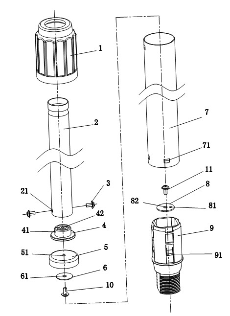
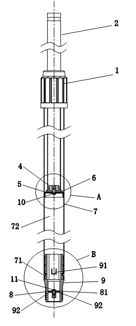
[0017] Such as Figures 1 to 5 As shown, a lifting mechanism for fans includes an outer joint assembly 1, an inner column tube 2 and an outer column tube 7, wherein the outer joint assembly 1 is screwed and fixed to the outer column tube 7 and the inner column tube 2 respectively, The present invention is characterized in that it also includes a piston device, a one-way valve device and a chassis joint 9, wherein the piston device is fixed at the lower end of the inner column tube 2; the upper end of the chassis joint 9 is fixed with the lower end of the outer column tube 7 and connected, the one-way valve device is fixed in the central cavity in the chassis joint 9, and several air holes 92 are provided on the central cavity in the chassis joint 9. In this embodiment, four air holes are provided, and the The number of air holes is set, and o...


PUM


Abstract

The invention relates to a lifting mechanism for fans, which comprises an outer joint component, an inner vertical pipe and an outer vertical pipe, and is characterized by further comprising a piston device, a one-way valve device and a base plate joint. The outer joint component is fixed with the outer vertical pipe and the inner vertical pipe in a screwed manner respectively, the piston device is fixed at the lower end of the inner vertical pipe, the upper end of the base plate joint is fixed and communicated with the lower end of the outer vertical pipe, the one-way valve device is fixed in a center cavity of the base plate joint, a plurality of air holes are arranged on the center cavity in the base plate joint, and one of the air holes is communicated with an air hole of the one-way valve device. The lifting mechanism for fans is simple in structure, small in number of assembling parts, low in manufacturing cost, favorable for large-scale manufacturing and production and fine in operational stability.

Description

technical field [0001] The invention relates to a lifting device for a fan column, which belongs to the improvement technology of a lifting mechanism for a fan. Background technique [0002] At present, when people use the fan, they sometimes use the lifting function in order to lift or lower the blowing height of the fan head; the lifting function of the fan column is currently fixed by a knob-like device to fix the inner tube and the outer tube; when in use, for To effectively fix the weight of the fan body, the knob will be over-tightened, so that when the lifting function is used again, the consumer needs to use both hands to forcefully twist the external knob. The weight is very heavy, which will cause the upper part of the fuselage to drop suddenly, and it is easy to pinch your hands at the bottom of the fan body or between the fan box and the external knob, making it unsafe to use; at the same time, the sudden drop of the fuselage will cause a lot of damage The sound...

Claims


Application Information

Patent Timeline
IPC IPC(8): F04D29/00
Inventor 韩永立陈宝君蒙鑫胡先意
Owner MIDEA GRP CO LTD
Learn More