Eureka AIR delivers breakthrough ideas for toughest innovation challenges, trusted by R&D personnel around the world.

Involute gear with concave and convex ring surfaces and method for designing and machining involute gear

A technology of involute gears and design methods, which is applied in the direction of belts/chains/gears, gear teeth, mechanical equipment, etc., can solve the problems of reduced load capacity, unstable transmission ratio, increased transmission error, etc., and achieve low processing costs , Improving the smoothness of motion and the effect of high tooth surface hardness

Active Publication Date: 2012-07-18
NANJING UNIV OF AERONAUTICS & ASTRONAUTICS
View PDF7 Cites 16 Cited by
  • Summary
  • Abstract
  • Description
  • Claims
  • Application Information

AI Technical Summary

Problems solved by technology

However, the involute gear transmission is more sensitive to such as axis parallelism error, axis cross angle error, axis cross error and cone apex position error, etc., so the phenomenon of gear pair edge contact, gear tooth interference, pressure angle change and other phenomena often occur, resulting in transmission The error increases, the transmission ratio is not constant, and the load capacity decreases, etc.

Method used


Image

  • Involute gear with concave and convex ring surfaces and method for designing and machining involute gear
  • Involute gear with concave and convex ring surfaces and method for designing and machining involute gear
  • Involute gear with concave and convex ring surfaces and method for designing and machining involute gear

Examples


Embodiment Construction

[0039] Below in conjunction with accompanying drawing, the present invention is described in further detail:

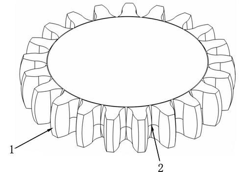
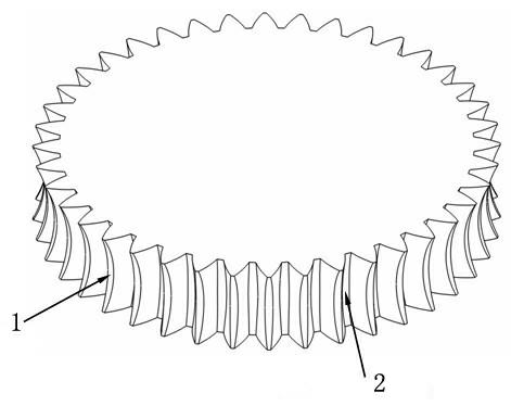
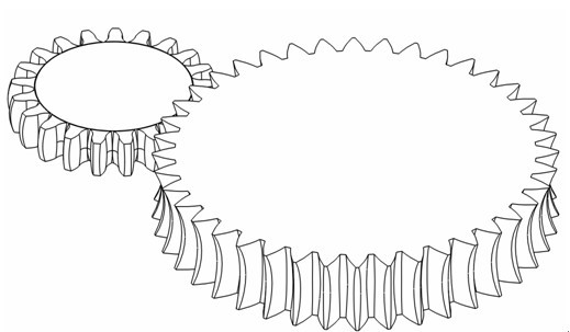
[0040] Such as figure 1 , 2 Shown: A toroidal involute gear is divided into two structural forms: convex toroidal involute gear and concave toroidal involute gear, which is characterized in that the curved surface of the tooth top and the curved surface of the dedendum are convex toroidal or concave toroidal A part of the surface, while the torus is formed by a circular arc rotating 360 degrees around the gear axis. The tooth profile curve of the end section of the gear tooth is an involute, which can realize a constant transmission ratio transmission. The tooth shape is distributed symmetrically about the midpoint of the tooth width. In each section along the tooth width direction, the thickness of the indexing circular tooth of the convex toroidal involute gear gradually decreases from the middle of the tooth width to both ends, while the thickness of the tooth to...


PUM


Abstract

The invention relates to a gear and a method for designing and machining the same. The gear is particularly characterized in that each of tooth crest curved surfaces and tooth root curved surfaces is a part of a convex ring surface or a concave ring surface, each of the tooth crest curved surfaces and the tooth root curved surfaces of the involute gear with the concave and convex ring surfaces is a part of a ring surface, an arc circularly rotates around an axis of the gear to form the ring surface, a tooth profile curve of the end section of each gear tooth is an involute, and the teeth are synchronously distributed around a center point of the tooth width. By the aid of the gear, three gear transmission forms can be realized, the gear not only can be used for driving of parallel axes, but also can be used for driving of intersecting axes with small axial intersect angles, high axis deflection installation errors are permitted when the gear is used for driving of parallel axes, the axial intersect angles are allowed to dynamically change when the gear is used for driving of intersecting axes, transmission ratio can keep constant when the gear is used for driving of parallel axes and driving of intersecting axes, and the gear teeth are not interfered with each other. By the aid of the method for designing the gear, the involute gear with the ring surfaces is divided into a plurality of tiny tapered involute gears, geometric parameter design of the involute gear with the ring surfaces is carried out, and a process of the method is carried out simply, conveniently and feasibly.

Description

technical field [0001] The invention relates to a gear and its design method and processing method, in particular to a gear whose tooth top curved surface and dedendum curved surface are part of a convex ring surface or a concave ring surface and its design and processing method. Background technique [0002] Involute gear transmission is the most widely used gear transmission in the world. It has many advantages such as constant transmission ratio, constant positive pressure direction between tooth profiles, separable motion and convenient processing. Therefore, although the involute tooth profile curve has been in existence for more than 200 years, it is still the most widely used tooth profile curve. However, the involute gear transmission is more sensitive to such as axis parallelism error, axis cross angle error, axis cross error and cone apex position error, etc., so the phenomenon of gear pair edge contact, gear tooth interference, pressure angle change and other phen...

Claims


Application Information

Patent Timeline
IPC IPC(8): F16H55/17F16H55/08B23F5/20
Inventor 刘雷黄因慧田宗军沈理达刘志东
Owner NANJING UNIV OF AERONAUTICS & ASTRONAUTICS
Why Eureka
Eureka Blog
Learn More