Refrigeration cycle method and system for 70MPa hydrogen filling station

A circulation system and refrigeration cycle technology, applied in pipeline systems, mechanical equipment, gas/liquid distribution and storage, etc., can solve the problems of no safe release pipeline, limited installation conditions, and defective safety performance in the cooling system, and achieve Optimizing energy consumption during the filling process, saving installation space, and flexible control of temperature rise

Inactive Publication Date: 2012-07-18
上海舜华新能源系统有限公司
View PDF5 Cites 9 Cited by
  • Summary
  • Abstract
  • Description
  • Claims
  • Application Information

AI Technical Summary

Problems solved by technology

However, this design has disadvantages such as large floor area, high coolant consumption, and relatively large installation

Method used


Image

  • Refrigeration cycle method and system for 70MPa hydrogen filling station
  • Refrigeration cycle method and system for 70MPa hydrogen filling station
  • Refrigeration cycle method and system for 70MPa hydrogen filling station

Examples


Embodiment Construction

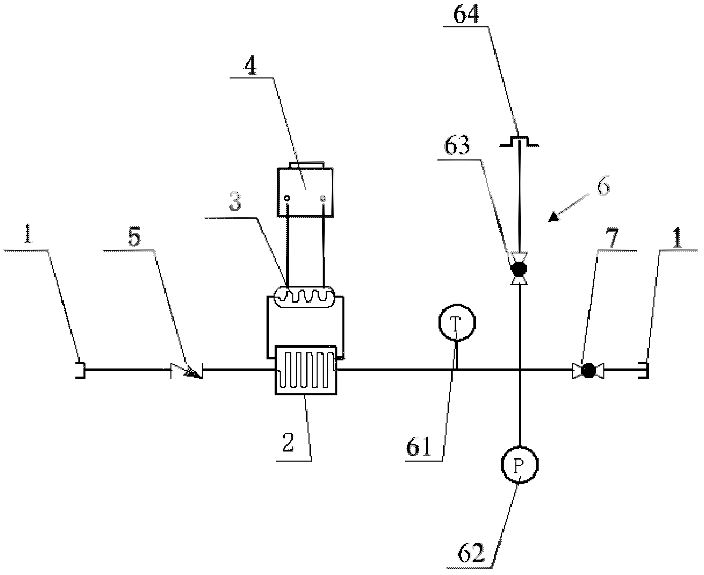
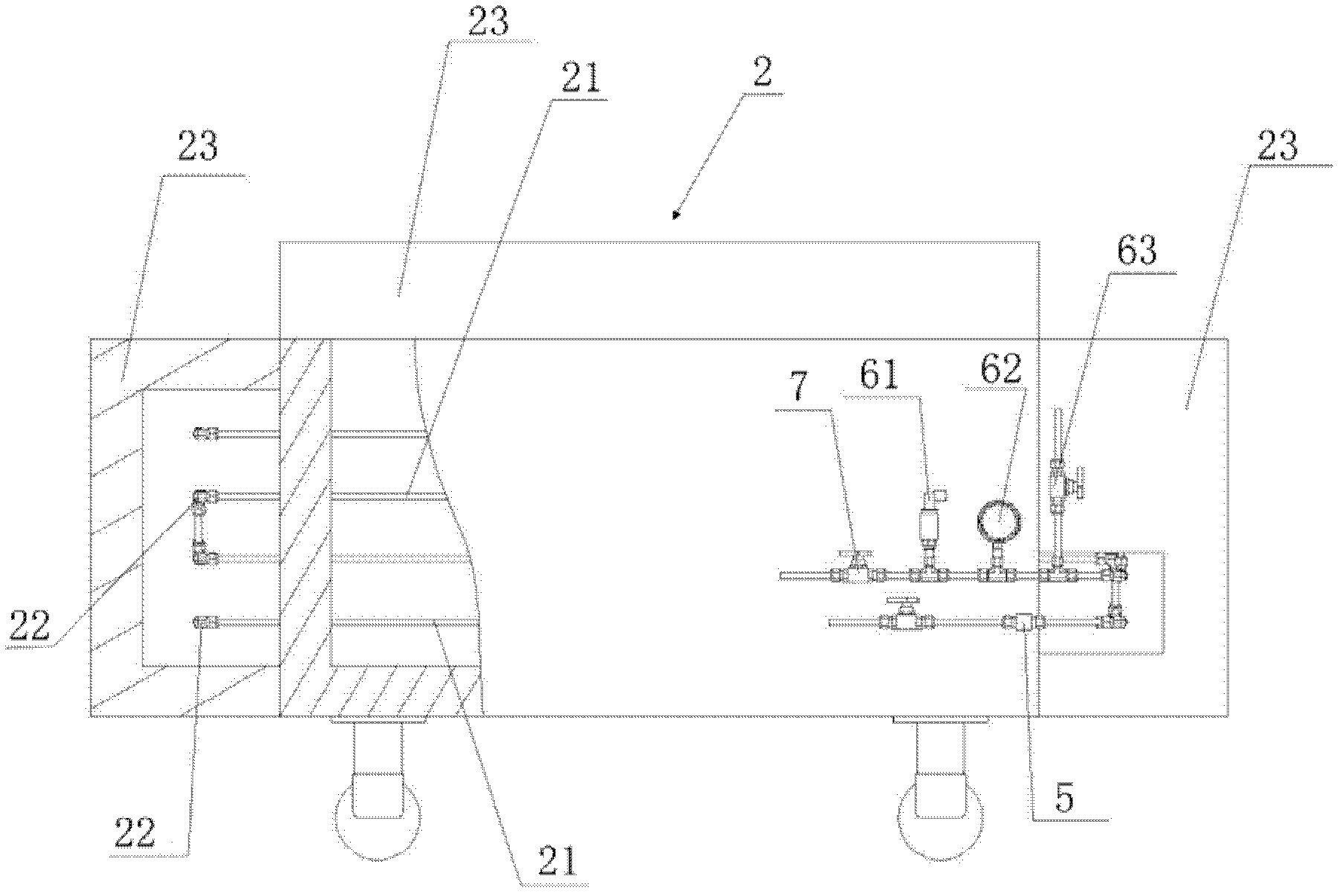
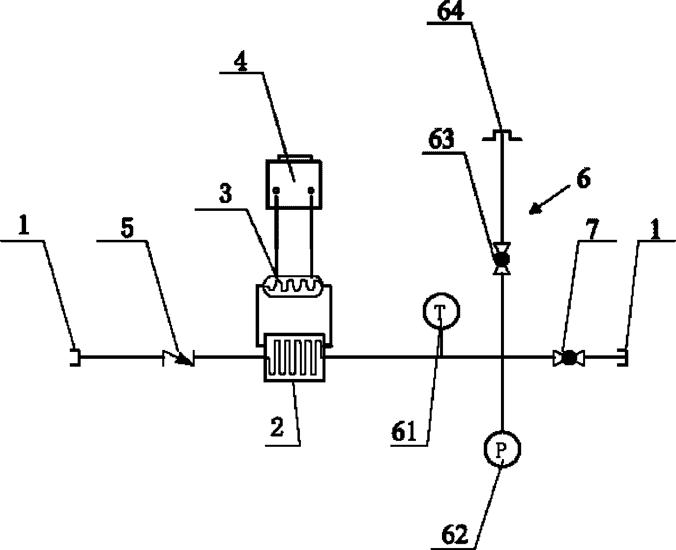
[0030] Such as figure 1 A refrigeration cycle system for a 70MPa hydrogen refueling station is shown, which includes: two quick-change joints 1, one of which is connected to a high-pressure hydrogen source and its booster pump, and the other is connected to a 70MPa hydrogen refueling machine; The first heat exchanger 2, in which the high-pressure hydrogen and the cooling liquid perform the first heat exchange; a second heat exchanger 3, in which a condensing agent is arranged, and the cooling liquid and the condensing agent after the first heat exchange are in the The second heat exchange is performed in the second heat exchanger 3; a refrigeration unit 4 is connected with the second heat exchanger 3, and the refrigeration unit 4 refrigerates the condensate in the second heat exchanger 3 through a compressor.

[0031] Further, the system also includes a safety relief device 6, which is arranged at the gas downstream outlet of the first heat exchanger 2, and is used for safely ...


PUM


Abstract

The invention relates to a refrigeration cycle method and a refrigeration cycle system for a 70MPa hydrogen filling station. The aim is to provide a refrigeration cycle method and a refrigeration cycle system for a 70MPa hydrogen filling station, which are convenient to install, are safe in usage and are low in cost. The method is in a double-refrigeration cycle, comprising the steps of primarily exchanging heat of the cooling liquid with the high pressure hydrogen; performing secondary heat exchange of the cooling liquid after heat exchange with a condensing agent to form a first double-refrigeration cycle; exchanging heat of the cooling liquid after secondary heat exchange with high pressure hydrogen, starting next double-refrigeration cycle. The refrigeration cycle system comprises a first heat exchanger where the high pressure hydrogen and the cooling liquid exchange heat primarily; a second heat exchanger provided with the condensing agent inside, the cooling liquid after primary heat exchange and the condensing agent exchange heat; a refrigerator set connected with the second heat exchanger and used for refrigerating the condensing agent in the second heat exchanger by a compressor.

Description

technical field [0001] The invention belongs to the field of new energy, and relates to a hydrogen precooling method for a hydrogen refueling station, in particular to a refrigeration cycle method and system for a 70MPa hydrogen refueling station. Background technique [0002] Fuel cell vehicle technology is a high-efficiency, zero-emission clean vehicle technology that uses hydrogen as fuel and converts hydrogen into electricity as a power source through fuel cells. Hydrogen is refueled through hydrogen refueling machines at hydrogen refueling stations, and stored in high-pressure hydrogen cylinders. The mainstream storage pressures are divided into 35MPa and 70MPa. [0003] The current hydrogen filling process is: hydrogen is stored in the storage tank of the hydrogen refueling station at a pressure higher than that of the on-board hydrogen storage bottle. After flowing through the hydrogenation machine and the solenoid valve, it enters the on-board hydrogen storage bottl...

Claims


Application Information

Patent Timeline
IPC IPC(8): F17D1/14F17D3/01
CPCY02E60/34
Inventor 高顶云李仕栋张金宝陈华强张圆锁刘绍军
Owner 上海舜华新能源系统有限公司
Why Eureka
Try Eureka