
Multifunctional mechanical tension and compression fatigue loading device and method

A fatigue loading and multi-functional technology, which is applied in the direction of applying repeated force/pulsation force to test the strength of materials, can solve the problems of poor test effect, high test cost, and expensive price, and achieve low test cost, long test period, The effect of low equipment cost

Inactive Publication Date: 2012-07-18
NANJING UNIV OF AERONAUTICS & ASTRONAUTICS
View PDF5 Cites 11 Cited by
  • Summary
  • Abstract
  • Description
  • Claims
  • Application Information

AI Technical Summary

Problems solved by technology

[0003] For a long time, it has been very difficult to achieve low-cost fatigue testing for this type of components
At present, it can be realized by hydraulic servo fatigue testing machine, but because these equipment are expensive, they have strict requirements on the use environment, and high energy consumption and long-term use require high test costs
[0004] Some current mechanical fatigue test loading devices simply adopt displacement control loading, so within the elastic range, the component deformation is small, and the accuracy of the load is completely realized by the displacement accuracy, coupled with the wear of the equipment during the fatigue test, so The accuracy requirements of the test load cannot be guaranteed, resulting in poor test results, especially for small-sized test pieces

Method used


Image

  • Multifunctional mechanical tension and compression fatigue loading device and method
  • Multifunctional mechanical tension and compression fatigue loading device and method
  • Multifunctional mechanical tension and compression fatigue loading device and method

Examples


Embodiment Construction

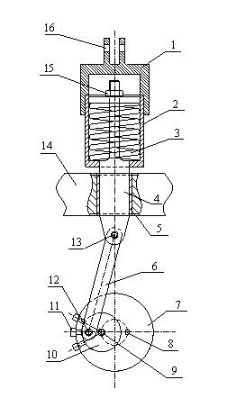
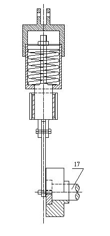
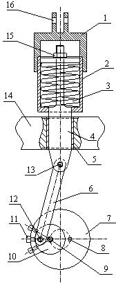
[0019] The accompanying drawings disclose, without limitation, the structural schematic diagrams of the preferred embodiments involved in the present invention; the technical solution of the present invention will be described in detail below in conjunction with the accompanying drawings.

[0020] Such as Figures 1 to 2 As shown, the mechanical tension-compression multifunctional fatigue loading device of the present invention includes a power source main shaft and a specimen loading connector, the power source main shaft is connected to one end of the pull piece through a double eccentric mechanism, and the other end of the pull piece is One end is connected to the connecting device of the test piece through an elastic tension-compression link mechanism; the double eccentric mechanism includes a main eccentric and a secondary eccentric; the main shaft of the power source is connected coaxially with the main eccentric, and the main shaft of the power source is connected to the...


PUM


Abstract

The invention relates to a multifunctional mechanical tension and compression fatigue loading device and method. The multifunctional mechanical tension and compression fatigue loading device comprises a power source main shaft, a test piece loading connecting member, a dual eccentric wheel mechanism, a tension piece and an elastic tension and compression connecting rod mechanism, wherein the elastic tension and compression connecting rod mechanism comprises a pressure connecting rod, an elastic element, a counter-force casing and dual loading inserting lugs. The method comprises the following steps of: rotating a secondary eccentric wheel; adjusting the position of an eccentric shaft of the secondary eccentric wheel according to the requirement and then locking the secondary eccentric wheel with a main eccentric wheel; starting a power source; sequentially adjusting the expansion amount of the elastic element through the main eccentric wheel, the secondary eccentric wheel, the tension piece and the pressure connecting rod; and rotationally adjusting nuts and further tuning the expansion mount of the elastic element to meet the loading requirement of the test piece. According to the multifunctional mechanical tension and compression fatigue loading device and method disclosed by the invention, the load error caused by wear of a structural element and mechanical clearance can be greatly reduced and the higher-precision repeated fatigue loading of the structural element is realized.

Description

technical field [0001] The invention relates to a mechanical tension-compression multifunctional fatigue loading device and a method thereof, which belong to the field of structural experimental mechanics. Background technique [0002] In aviation, navigation, transportation, road and bridge, building, and port engineering structures, beams and elastic elements of various materials are typical stressed components, and they are all under repeated stress in various environments for a long time, so this type of components Fatigue strength in various environments is an important research topic in structural mechanics. Especially in the design of modern engineering structures, it is necessary to study the strength of components under complex environments and loads. It is urgent to realize such loads and environmental states in the laboratory to assess the fatigue strength of components and make a contribution to the next step of theoretical establishment. Prepare. [0003] For ...

Claims


Application Information

Patent Timeline
IPC IPC(8): G01N3/34
Inventor 汪勇蔡晨宁汪浩文耿飞汤剑飞刘丽娜
Owner NANJING UNIV OF AERONAUTICS & ASTRONAUTICS
Learn More