High-temperature fused salt synchrotron radiation in-situ research device

A high-temperature molten salt, in-situ technology, used in measuring devices, material analysis using wave/particle radiation, instruments, etc., can solve problems such as large surface tension, testing, and destroying the original state of molten salt, and achieve a high detection angle. , uniform heating, good sealing effect

Inactive Publication Date: 2012-07-18
SHANGHAI INST OF APPLIED PHYSICS - CHINESE ACAD OF SCI
View PDF3 Cites 41 Cited by
  • Summary
  • Abstract
  • Description
  • Claims
  • Application Information

AI Technical Summary

Problems solved by technology

[0009] Although the devices of the above two research groups have some advantages, there are two main problems in their design: one is that their sample pools all adopt the method of adsorbing high-temperature molten salt with high-melting point BN powder as the skeleton. It is in a thin film state, and there is a large surface tension effect,

Method used


Image

  • High-temperature fused salt synchrotron radiation in-situ research device
  • High-temperature fused salt synchrotron radiation in-situ research device
  • High-temperature fused salt synchrotron radiation in-situ research device

Examples


Embodiment Construction

[0048] The high-temperature molten salt synchrotron radiation in-situ research device of the present invention will be further described in detail below in conjunction with the accompanying drawings and specific examples.

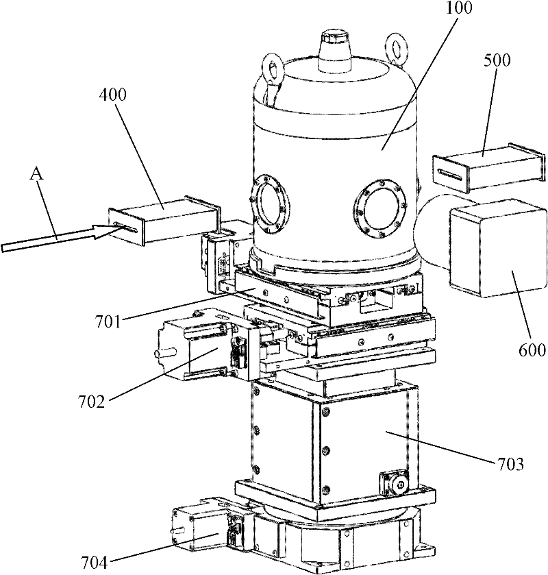
[0049] figure 1 It shows the structure of the high-temperature molten salt synchrotron radiation in-situ research device described in the invention in this embodiment. Such as figure 1 As shown, the vacuum furnace 100 is set on the positioning platform, and the furnace wall is respectively provided with an incident window, a transmission window and a fluorescent window, wherein the incident window and the transmission window are arranged coaxially and collinearly, and the axis of the fluorescent window is aligned with the incident window and the transmission window. axis vertical. The molten salt test tube and the heating device are set in the cavity of the vacuum furnace 100 (such as Figure 4 , Figure 5 shown). The positioning stage adjusts the posi...


PUM

PropertyMeasurementUnit
The inside diameter ofaaaaaaaaaa
Outer diameteraaaaaaaaaa

Abstract

The invention discloses a high-temperature synchrotron radiation in-situ research device. The high-temperature fused salt synchrotron radiation in-situ research device comprises a fused salt test tube, a vacuum furnace, a heating device, a first ionization chamber, a second ionization chamber or a charge coupled device (CCD) detector and an external fluorescence detector, wherein a cavity is formed in the vacuum furnace; an incident window, a transmission window and a fluorescence window are arranged on the furnace wall of the vacuum furnace; the incident window and the transmission window are arranged coaxially and collinearly; the axial line of the fluorescence window is vertical to that of the incident window and/or the transmission window; the heating device is arranged in the cavity of the vacuum furnace and is used for heating the fused salt test tube arranged in the heating device; an incident hole, a transmission hole and a fluorescence hole corresponding to the incident window, the transmission window and the fluorescence window respectively are formed on the heating device; the first ionization chamber corresponding to the incident window is arranged outside the vacuum furnace; the second ionization chamber or the CCD detector corresponding to the transmission window is arranged outside the vacuum furnace; and the external fluorescence detector corresponding to the fluorescence window is arranged outside the vacuum furnace.

Description

technical field [0001] The invention relates to a radiation in-situ research device, in particular to a synchrotron radiation in-situ research device. Background technique [0002] With the rapid economic development, energy consumption and demand are also increasing. Vigorously developing nuclear energy is one of the most effective ways to solve high energy consumption. The thorium-based nuclear energy system based on the thorium-uranium fuel cycle has the advantages of rich resources, less nuclear waste, good nuclear non-proliferation, and good adaptability. One of the leading directions. Unlike the other five Generation IV nuclear reactors that use solid fuel rods as fuel, it uses high-temperature liquid molten salt as fuel. Due to the fluidity of the fuel, there is no need to use cooling water or liquid metal as a fuel coolant to exchange heat with solid fuel rods, and the liquid fuel can directly enter the heat exchanger for heat exchange. The main components of mol...

Claims


Application Information

Patent Timeline
IPC IPC(8): G01N23/223
Inventor 何上明李爱国闫帅李晓丽林建波邹杨余笑寒
Owner SHANGHAI INST OF APPLIED PHYSICS - CHINESE ACAD OF SCI
Why Eureka
Try Eureka