Ground source heat pump rock-soil heat response dynamic testing system and testing method

A dynamic test, ground source heat pump technology, applied in the direction of material thermal development, etc., can solve the problems of inability to understand the heat transfer of soil layers in detail, time-consuming, and inability to directly understand the interaction between wells and other wells.

Inactive Publication Date: 2012-07-18
UNIV OF SHANGHAI FOR SCI & TECH
View PDF2 Cites 24 Cited by
  • Summary
  • Abstract
  • Description
  • Claims
  • Application Information

AI Technical Summary

Problems solved by technology

[0005] The present invention provides a new type of ground source heat pump rock soil therma

Method used


Image

  • Ground source heat pump rock-soil heat response dynamic testing system and testing method
  • Ground source heat pump rock-soil heat response dynamic testing system and testing method
  • Ground source heat pump rock-soil heat response dynamic testing system and testing method

Examples


Embodiment 1

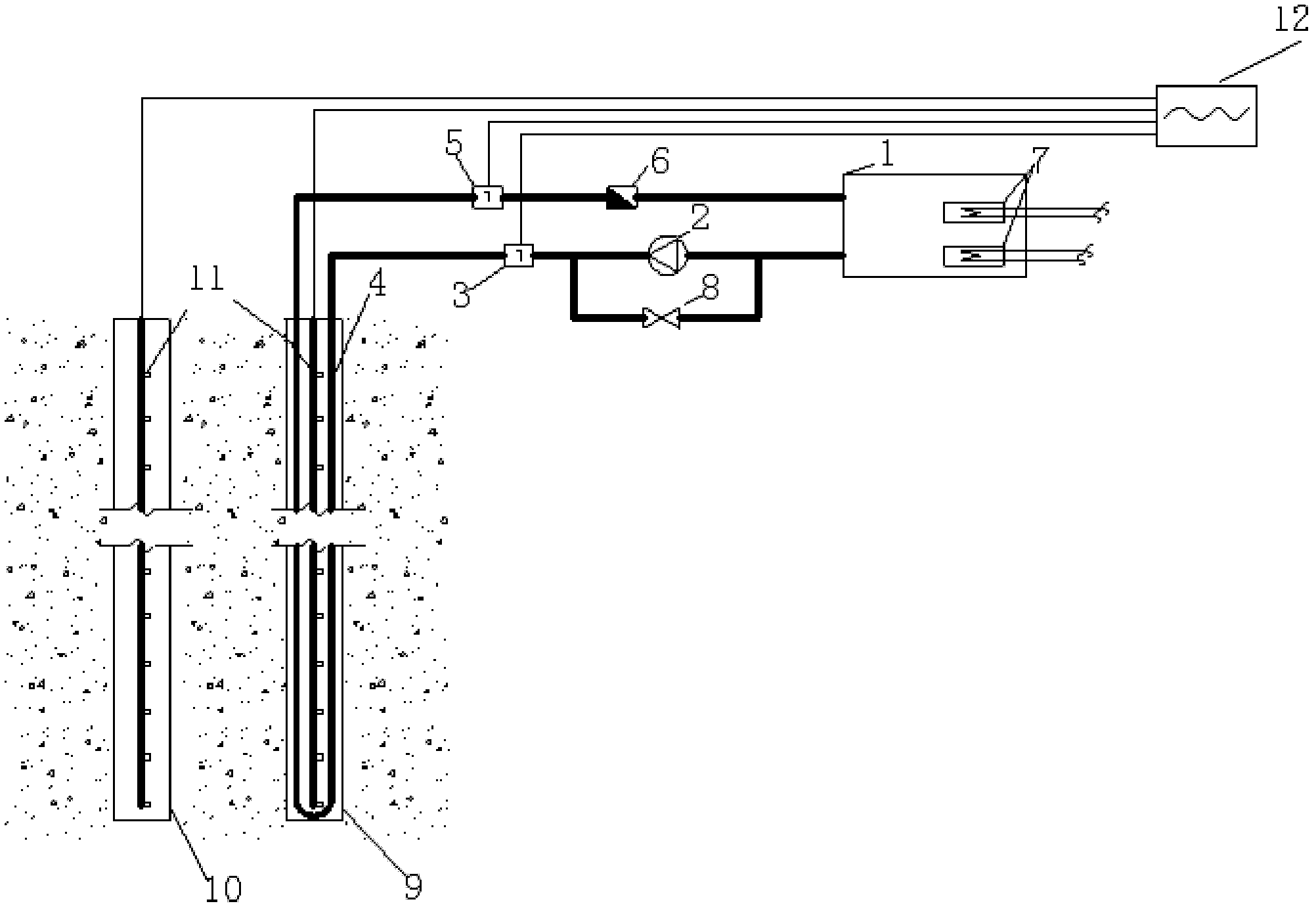
[0025] The depths of the heating well 4 and the temperature monitoring well 10 are both 100m (the depth of the heating well can also be less than the depth of the monitoring well during actual implementation), and the apertures of the wells are both 130mm. The heating well adopts a single U-shaped pipe with a pipe diameter of DN32, and the heating well 4 and the temperature monitoring well 10 are generally at a distance of 0.3m to 1.2m, which is 0.7m in this embodiment, and the same temperature sensor group 11 is arranged in the two wells, that is, a series of temperature sensors with the same interval are arranged at the same depth. Embodiment The distance between the temperature sensors in the depth direction is 10m.

[0026] The measurement process is as follows: (1) Initial temperature test of rock and soil: After completing the heating well and temperature monitoring well, record the values ​​of the temperature sensor group in the heating well and temperature monitoring we...

Embodiment 2

[0043]The distance between the heating well 4 and the temperature monitoring well 10 is 0.3m, and the others are consistent with the first embodiment.

Embodiment 3

[0045] The depth of the heating well 4 is 100m, the depth of the temperature monitoring well 10 is 98m, the distance between the heating well 4 and the temperature monitoring well 10 is 1.2m, and the others are consistent with the embodiment 1.

[0046] The backfilling of the heating well and the temperature monitoring well should be backfilled with original slurry; because the linearity and stability of the platinum resistance sensor are the best among the commonly used temperature sensors, the probes of the temperature sensor group described in this example use high-precision Platinum resistors for improved accuracy.


PUM


Abstract

The invention relates to a ground source heat pump rock-soil heat response dynamic testing system, which consists of a heating water tank, a circulating pump, a bypass-valve, a heating well, a U-shape pipe, a temperature monitoring well, a data acquisition analyzer, temperature sensors, flow sensors and a heater, and is characterized in that the temperature monitoring well is arranged in the position 0.3-1.2 m away from the heating well, a temperature sensor group identical to temperature sensors group on the heating well is arranged in the temperature monitoring well, and all the temperature sensors and flow sensors are connected with the data acquisition analyzer through signal lines. In testing, a rock-soil original temperature value data test, a basic heating process data test, a strengthened heating process data test and after heating stop data test are respectively carried out on the heating well and the temperature monitoring well. By the comparison of a calculation value and a measured value of a heat transfer model and the revision of rock-soil thermal conductivity, the actual rock-soil thermal productivity is ultimately approximated. The rock-soil temperatures in the heating well and the temperature monitoring well are monitored synchronously to shorten the test time; and the heat transfer conditions of rock-soil at different depths and the mutual influence of wells are accurately mastered to provide data for designing.

Description

technical field [0001] The invention relates to a ground source heat pump rock soil thermal response dynamic testing system and a testing method, belonging to the technical field of thermal physical property testing of deep rock soil. Background technique [0002] Today, with the rapid development of my country's economy, the problem of energy shortage has become increasingly severe. Air-conditioning energy consumption accounts for a large proportion of building energy consumption. Energy conservation, emission reduction and development of new energy sources are of great significance. The deep rock and soil have a stable temperature, which is lower than the air temperature in summer and higher than the air temperature in winter. The rock and soil source heat pump technology uses rock and soil as a low-grade heat source and heat sink. Heat release, its energy efficiency is significantly improved compared to air source heat pumps. Testing the thermophysical parameters of rock...

Claims


Application Information

Patent Timeline
IPC IPC(8): G01N25/20
Inventor 于国清赵彦杰高炳春陶勤练
Owner UNIV OF SHANGHAI FOR SCI & TECH
Why Eureka
Try Eureka