Drum membrane type optical fiber splicer capable of being repeatedly opened to be used

A technology of optical fiber connectors and tympanic membranes, which is applied in the field of optical fiber connectors, can solve the problems of V-shaped blocks that are easy to scratch, not vertical, and cannot be sealed, so as to avoid pollution and erosion, prolong service life, and prevent optical fibers from being pressed off. Effect

Active Publication Date: 2012-07-18
NANJING XIUDEA COMM TECH CO LTD
View PDF7 Cites 9 Cited by
  • Summary
  • Abstract
  • Description
  • Claims
  • Application Information

AI Technical Summary

Problems solved by technology

[0004] In the fixing of optical fiber, in the first optical fiber fixing method, when the metal sheet is aligned with the metal sheet in the fixing mechanism, a return groove must be set on the opposite side of the V-shaped groove to prevent the optical fiber from being pressed off. The gap between the optical fiber is controlled by the folded metal sheet. The space in the cavity guarantees the opening, that is, the V-groove gap (fiber threading gap), which brings great manufacturing difficulty and low yield; in the second optical fiber fixing method, the plastic V-shaped block alignment mechanism is in the lock When tightening the optical fiber, the gland rotates to compress the optical fiber in the V-shaped groove. Due to the impact of the gap drift of the gland through the rotation and compression method, the direction of the optical fiber is often not perpendicular to the V-shaped groove, and the error of the alignment accuracy of the optical fiber This will increase the connection loss of the two connected optical fibers; when the optical fiber channel of the plastic V-shaped block alignment mechanism is used repeatedly, a special key needs to be used to push the pressure block away. Difficulty, low yield, and the plastic debris generated by friction during the push-off process pollutes the splicing point, which affects light transmission during repeated use, resulting in a decline in splicing quality; the initial state of some plastic V-shaped block alignment mechanisms is free, and the optical fiber When threading, it is necessary to open the V-shaped block channel, and the matching liquid is adsorbed in it. When the optical fiber penetrates into the top-opened V-shaped groove, the fiber threading resistance increases, and the probability of false docking in the project increases. In addition, the sharp fiber cutting end face is very difficult. It is easy to scratch the V-shaped block, causing debris to pollute the splicing point, resulting in splicing failure; in the third optical fiber fixing method, because the floating block is designed as a threshold, when it is pressed down by the cover, the floating block is affected by plastic deformation. While rotating the crimped fiber, rub it downwards to make the optical fiber in the V-groove vibrate. The force direction of the fiber is not perpendicular to the V-groove, which will lead to poor alignment accuracy of the spliced ​​fiber and increased splicing loss. Due to alignment Accuracy is affected by materials and interference accuracy, and the dispersion of alignment accuracy is large, resulting in poor repeatability of optical fiber splicing
[0005] The common disadvantage of the first two optical fiber fixing methods is that the V-shaped groove cannot be sealed, and there is no matching night storage chamber, which causes the matching liquid used in the V-shaped groove to be easily polluted and lost, directly affecting the life of the connection. Although it can have a certain sealing effect in the working state, it cannot be sealed before use, and the opened gland is easy to slip during repeated use, and it is easy to be polluted by the environment during repeated use.

Method used


Image

  • Drum membrane type optical fiber splicer capable of being repeatedly opened to be used
  • Drum membrane type optical fiber splicer capable of being repeatedly opened to be used
  • Drum membrane type optical fiber splicer capable of being repeatedly opened to be used

Examples


Embodiment Construction

[0043] The present invention will be described in detail below in conjunction with the accompanying drawings.

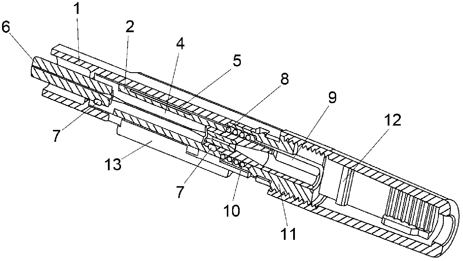
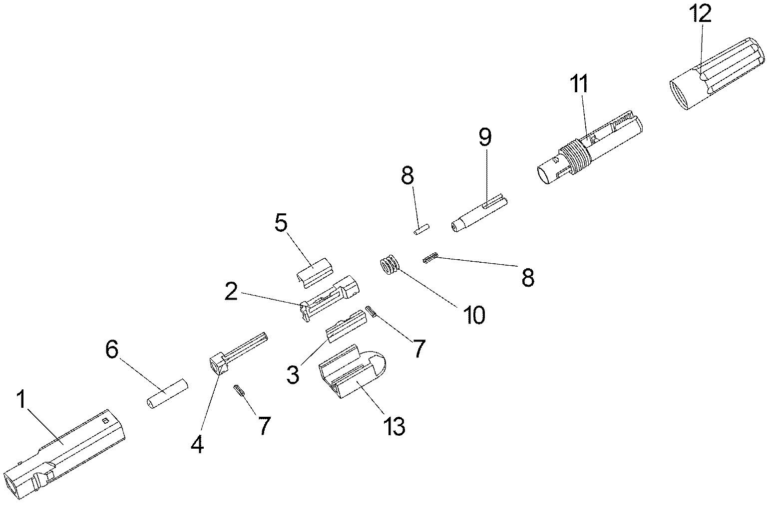
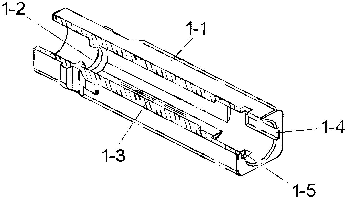
[0044] Such as figure 1 , 2 , 3, 4, 6, 9, 11, 12, 13,

[0045] Including ferrule assembly 14, box assembly 15, housing assembly 16, spring 10 and opening cover 13, the ferrule assembly 14 includes ferrule 6, latch 7, V-shaped groove body 4, V-shaped The front end of the tank body 4 is provided with a front connection cavity 4-4, and the front connection cavity 4-4 is connected with the ferrule 6 through a latch 7; the box assembly 15 includes a box body 2, a box cover 3, a spring clip 5, The plug 7, the wire block 8 and the wire body 9 are provided with a tympanic cavity 2-1 in the box body 2, and a tympanic membrane 2-2 is arranged in the middle of the tympanic cavity 2-1, and there are floating ribs 2-2 around the tympanic membrane 2-2. 3. The V-shaped groove 4-1 in the ferrule assembly 14 is partially inserted into the tympanic cavity 2-1, and the V-shaped groo...


PUM


Abstract

The invention discloses a drum membrane type optical fiber splicer capable of being repeatedly opened to be used. The drum membrane type optical fiber splicer capable of being repeatedly opened to be used comprises an insertion core assembly, a box assembly, a shell assembly, a spring and an opening cover; the insertion core assembly and the box assembly are packaged in the shell assembly; the spring is arranged between the box assembly and the shell assembly; the box assembly comprises a box, a box cover, a guide wire block and a guide wire body; the box comprises a box body which is provided with a drum membrane cavity; two ends of the drum membrane cavity are communicated with the insertion core and guide blocks respectively; the side of the drum membrane cavity is provided with a drum membrane which is pressed to reduce the cross-sectional area of the drum membrane cavity; the periphery of the drum membrane is connected with the box body through a floating rib; a V-shaped groove is formed in the drum membrane cavity; and the box cover acts on the drum membrane through a locking membrane. The fixing action force which is applied by the optical fiber splicer to spliced optical fibers is distributed in a balanced way, and the twisting misplacement of the spliced optical fibers can be avoided; and moreover, a structure of sealing splicing points is adopted, so the splicing points are clean, and the erosion and interference of pollution can be avoided.

Description

technical field [0001] The invention relates to a connection device for optical fiber installation, which seals the V-shaped groove part of the ferrule assembly in the tympanic cavity, drives the tympanic membrane with a spring clamp to compress the optical fiber, and can be opened and used repeatedly. Fiber splices with pre-preset or non-preset fiber splicing methods. Background technique [0002] At present, there are mainly three ways to fix the optical fiber in the quick connection device products for re-openable use. [0003] The first is to align and fix the two optical fiber ends by pressing the folded metal sheet to realize the butt end of the optical fiber; the second is to realize the butt end of the optical fiber by pressing and fixing the plastic block to fix the optical fiber; the third is to achieve the end of the optical fiber by The box-built gland presses the floating block to compress the V-shaped block to fix the optical fiber to realize the butt-end of t...

Claims


Application Information

Patent Timeline
Patent Type & Authority Applications(China)
IPC IPC(8): G02B6/38G02B6/36
CPCG02B6/36G02B6/38G02B6/3898G02B6/3846G02B6/3806
Inventor 李响
Owner NANJING XIUDEA COMM TECH CO LTD
Why Eureka
Try Eureka