[0017] The present invention will be described in detail below with reference to the drawings and embodiments.
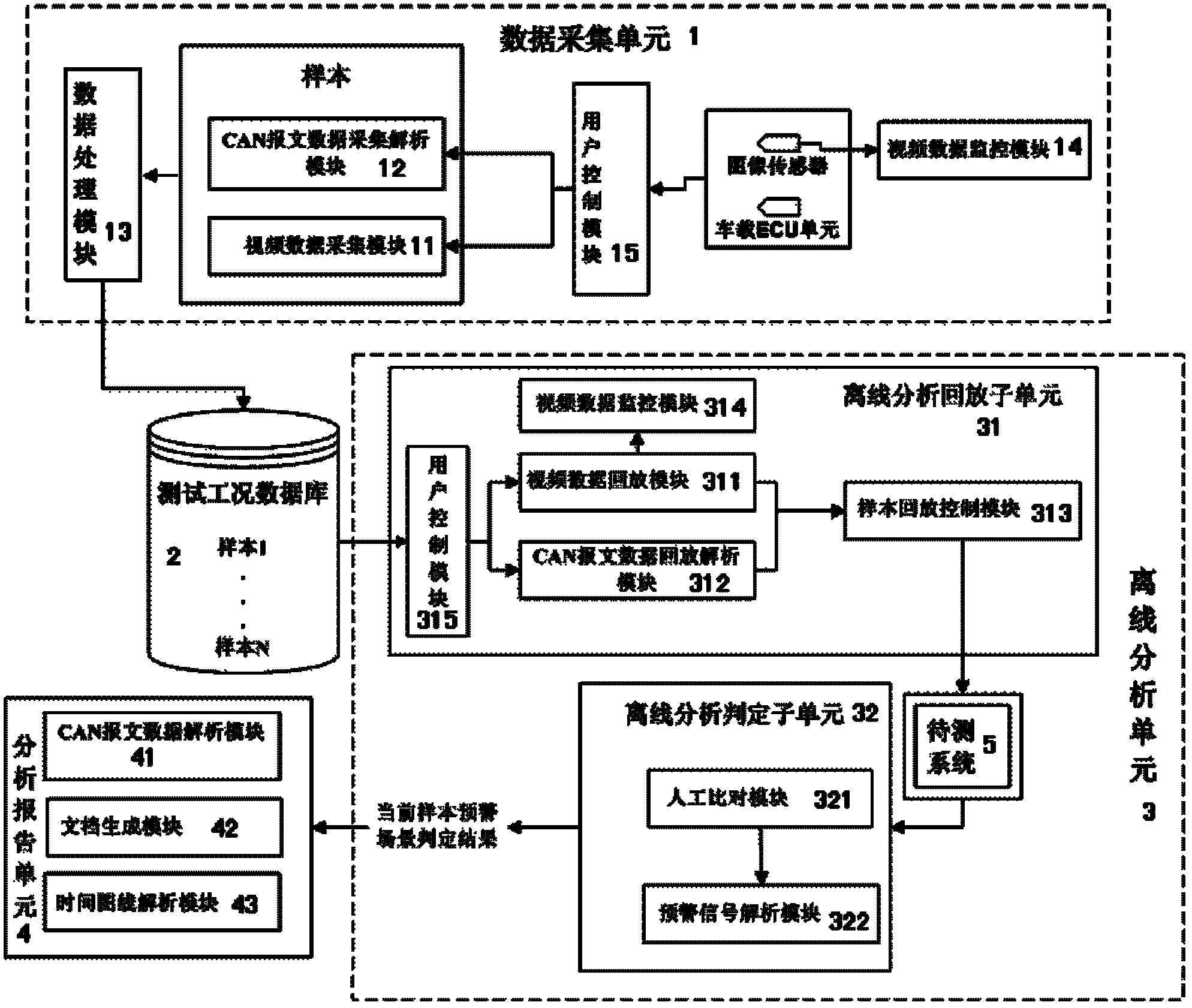
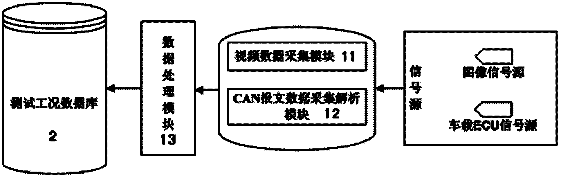
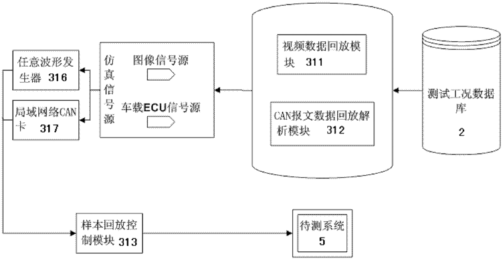
[0018] Such as figure 1 As shown, the test platform of the present invention includes a data acquisition unit 1, a test condition database 2, an offline analysis unit 3, and an analysis report unit 4. The offline analysis unit 3 includes an offline analysis playback subunit 31 and an offline analysis Decide subunit 32. The test platform of the present invention is divided into two stages when in use, namely obtaining samples and testing the early warning function of the system under test.
[0019] When obtaining samples, the test platform needs to be set up in the cockpit of the test vehicle. The power terminal of the test platform is connected to the on-board inverter of the test vehicle with an output power of more than 850W. The on-board inverter provides 220V AC power for the test platform. Time data collection unit 1 collects the road environment video information and the vehicle state information of the experimental vehicle at different times during the driving process of the experimental vehicle, and saves the road environment video information collected at the same time and the vehicle state information of the experimental vehicle to the same A sample is formed in the array, and the data acquisition unit 1 sends and saves all the samples corresponding to different moments in the test condition database 2.
[0020] When testing the early warning function of the system under test, the test platform is in the offline stage, and the samples extracted by the offline analysis and playback subunit 31 from the test condition database 2 are sent to the system under test 5 as simulation data, and the system under test 5 generates an early warning signal The early warning signal is generated under the conditional simulation environment, the offline analysis and playback subunit 31 sends the generated early warning signal and the samples corresponding to the early warning signal to the offline analysis and judgment subunit 32, and the offline analysis and judgment subunit 32 comprehensively analyzes the road environment video Information, the state information of the vehicle's own vehicle and the early warning signal are judged, the judgment result of the early warning scene corresponding to the current sample is generated, and the judgment result is sent to the analysis report unit 4, and the analysis report unit 4 analyzes the judgment result of the current sample early warning scene , Generate analysis graph and judgment result document.
[0021] In the above embodiment, the road environment video information is the road image information in front of the test vehicle, and the vehicle state information of the test vehicle is the left and right turn signals contained in the on-board ECU unit, and real-time vehicle speed and brake pedal information.
[0022] Such as figure 1 , figure 2 As shown, in the foregoing embodiments, the data collection unit 1 includes a video data collection module 11, a CAN message data collection and analysis module 12, a data processing module 13, a video data monitoring module 14 and a user control module 15; The input end of the video data acquisition module 11 is connected to the output end of the graphics sensor set above the experimental vehicle, and the input end of the CAN message data acquisition and analysis module 12 is connected to the vehicle OBD interface of the experimental vehicle, that is, the vehicle ECU unit bus interface, and the video data acquisition module The output terminal of 11 and the output terminal of the CAN message data acquisition and analysis module 12 are respectively connected to the input terminal of the data processing module 13, the output terminal 13 of the data processing module is connected to the input terminal of the test condition database 2, and the input terminal of the video data monitoring module 14 The output end of the image sensor is connected to the output end of the road environment to monitor the state of the video information of the road environment. At the same time, the input ends of the video data acquisition module 11 and the CAN message data acquisition and analysis module 12 are respectively connected to the output end of the user control module 15 to monitor the road environment video. The sampling rate, sampling time, storage path and storage format of information and CAN message data are set to synchronize the time sequence of road environment video information and CAN message data. The storage format of road environment video information is AVI, CAN message data The storage format is a txt file.
[0023] When starting to collect data, the video data collection module 11 will simultaneously send the collected road environment video information and the self-vehicle status information collected by the CAN message data collection and analysis module 12 to the data processing module 13, and the data processing module 13 will receive it at the same time The road environment video information and self-vehicle status information of the segment are respectively named according to the collection time, and all road environment video information and self-vehicle status information marked in the same time period are saved into an array to form a single copy to complete a data collection After that, the data processing module 13 sends the collected samples to the test condition database. Among them, the video data acquisition module 11 can be a digitizer PXI-5122, and the CAN message data collection and analysis module 12 can be a PXI-8513/2 LAN. Network CAN card, the data processing module 13 can adopt the embedded controller PXI-8108, the video data monitoring module 14 can adopt the PCI-1409 board card, all devices can set their working parameters through the user control module 15 before collecting data. The external communication interfaces of PXI devices all adopt the common BNC interface, SMB interface, DB-9 interface, RCA interface.
[0024] In each of the above embodiments, the test condition database can be a folder with a user-defined path, located in the internal integrated hard disk of the embedded controller PXI-8108, and contains all collected road environment video information and self-vehicle status CAN messages Data information.
[0025] In the foregoing embodiments, the offline analysis playback subunit 31 includes a video data playback module 311, a CAN message data playback analysis module 312, a sample playback control module 313, a video data monitoring module 314, and a user control module 315; The input terminals of the video data playback module 311 and the CAN message data playback analysis module 312 are respectively connected to the output terminal of the test condition database 2, and the output terminal of the video data playback module 311 is connected to the input terminal of an arbitrary waveform generator 316, CAN message The output end of the data playback analysis module 312 is connected to the input end of a local area network CAN card 317. The output ends of the arbitrary waveform generator 316 and the local area network CAN card 317 are connected to the input end of the system under test through the sample playback control module 313, and the video The input terminal of the data monitoring module 314 is connected to the output terminal of the video data playback module 311, and the input terminals of the video data playback module 311 and the CAN message data playback analysis module 312 are also connected to the user control module 315 respectively, to determine the sample extraction path and playback time , Conversion rate, error prompt, CAN message parsing, DBC file import, etc. to be set.
[0026] When replaying the sample data, the arbitrary waveform generator 316 sends the road environment video information in the acquired sample to the system under test 5, which replaces the image sensor of the system under test as the simulation video signal source. At the same time, the LAN CAN card 317 connects the same The sample's experimental vehicle state data is also sent to the system under test 5, which replaces the on-board ECU unit as the simulation message signal source. The system under test 5 makes it work in the simulated road environment according to the simulation video signal source and the simulation message signal source. The system under test 5 generates an early warning signal based on road environment information and vehicle status information. The sample playback control module 313 controls the playback, pause, and playback of the sample data, and the video data monitoring module 314 monitors the reasonable environment in the sample. The state of the video information is controlled. The arbitrary waveform generator 316 can be PIX-5421, and the local area network CAN card 317 can be PXI-8513. Both can use the user control module 315 for initial settings of their ports and operating parameters.
[0027] Such as Figure 4 As shown, in the foregoing embodiments, the offline analysis and determination subunit 32 includes a manual comparison module 321 and an early warning signal analysis module 322. The manual comparison module 321 includes a lane departure alarm correct recording unit, a lane departure alarm false alarm recording unit, a lane departure alarm false alarm recording unit, a front collision alarm correct recording unit, a front collision alarm false alarm recording unit, and The forward collision alarm missed report recording unit, the input end of the early warning signal analysis module 322 is connected to the alarm signal output end of the system under test 5 through the LAN CAN card 317. The tester compares the simulation data of the test condition database 2 played back to the system under test and the scene of the alarm information of the system under test 5 through the manual comparison module 321, and judges each alarm as positive, false and false , And send the judgment result to the early warning signal analysis module to record the time of judgment and the number of each judgment result in the time period corresponding to this sample, that is, the tester judges the nature of the alarm according to the alarm situation of the system under test, and the early warning signal analysis module records The meaning of each judgment and the time relative to a sample playback period are recorded in a document format. For example, a sample is 6 minutes long and the lane departure alarm is correct at 1 minute and 20 seconds. The early warning signal analysis module will record " Sample number, 00:01:20, **The lane departure warning is correct". In the offline analysis stage, the tester compares the alarm signals generated by each sample played back to the system under test. After each sample is completed, the comparison is called "one test completed". After the data is processed through the early warning signal analysis module Send the judgment result to the analysis report unit 4.
[0028] In the foregoing embodiments, the analysis report unit 4 includes a CAN message data analysis module 41, a document generation module 42 and a time chart line analysis module 43. The analysis report unit 4 generates graphs and documents for each test according to the recorded system warning signals and judgment results, mainly including: 1) The nature of the sample alarm that is played back each time, and the nature includes the left and right lane departure alarm of the test sample- Time curve, forward collision alarm-time curve; 2) The nature of each playback sample, including the left and right turn signal-time curve, brake-time curve, and vehicle speed-time curve in this playback sample; 3) System under test The alarm performance of this playback includes the judgment result of whether the tester’s early warning response of the system to be tested is correct, whether it is false positive, whether it is false negative, and the display format is "sample number, **hour**minute**second , **The alarm is correct or false or false". Among them, the CAN message analysis module 41 deals with the left and right turn signals, vehicle speed, brake pedal signals and the warning signals of the system under test in the current sample for the left and right turn signals of the vehicle status information in the current sample. The time and number of occurrences. The CAN message of the above-mentioned signals enables all the above-mentioned signals to be synchronized in time to ensure that the time chart analysis module 43 can work normally. The display form of the document generation module 42 is "sample number, specific time, alarm Result", the time graph analysis module 43 uses the time of the current playback sample as a benchmark to display various data curves of the experimental vehicle, including vehicle speed-time curve, alarm time-time curve, turn signal-time curve, brake signal-time Curve, alarm-time curve of the system under test.
[0029] Such as Figure 5 As shown, in the foregoing embodiments, the operating platform of the present invention may adopt a LABVIEW virtual instrument. In order for the tester to facilitate the judgment of the alarm nature of the system under test, a corresponding display unit can be set on the operating platform interface to display the test process and the judgment result in real time. On the running platform interface, you can set a pause/play virtual button corresponding to the sample playback control module. In the offline analysis unit, click "Pause/Play" on the operation interface to control the playback progress of the sample. There is also a video observation area in the center of the operation interface. 6 and a virtual vehicle speed display table 7, the video observation area 6 can display the road environment video information, the virtual vehicle speed display table 7 can analyze the real-time vehicle speed of the vehicle state; two virtual turn signals 80, 81 are set above the video observation area 6 , And a virtual brake light 82 is set between the two turn signals 80 and 81. The turn lights are mainly used to analyze the left and right turn signal signals of the own vehicle state, and the brake lights analyze the brake signal of the own vehicle state; below the video observation area 6 There are virtual lane departure warning lights 90 and 91, and a virtual anti-collision warning light 92 is arranged between the lane departure warning lights 90 and 91. The anti-collision warning light analyzes the anti-collision warning signal output by the system under test. The lower part of the operation interface is provided with a judgment result display area. The judgment result display area includes a display area indicating the lane departure alarm judgment result and a display area indicating the anti-collision alarm judgment result. There are six display lights corresponding to the manual comparison module. Lane departure Both the alarm judgment result display area and the rear-end collision prevention alarm judgment result display area are equipped with correct, false alarm and missed alarms.
[0030] The above-mentioned embodiments are only used to illustrate the present invention. The names and signal transmission methods of each module can be changed. Any equivalent transformations and improvements based on the technical solutions of the present invention should not be excluded. Outside the protection scope of the present invention.