
User-side peak-shaving power storage and supply system and method

A power supply system and user-side technology, applied in the direction of power network operating system integration, information technology support system, electrical components, etc., can solve the damage of power grid maintenance personnel and equipment facilities, increase power grid distribution scheduling management, waste resources and investment and other issues, to achieve the effect of improving resource utilization, active and effective power grid peak regulation, and reducing the use of peak price electricity

Active Publication Date: 2012-07-18
IPS TECH LTD
View PDF4 Cites 13 Cited by
  • Summary
  • Abstract
  • Description
  • Claims
  • Application Information

AI Technical Summary

Problems solved by technology

[0003] In daily practice, the power supply and consumption agreement is currently adopted between the power department and the user. Whether it is the power department or the user, as far as the agreement is concerned, the total amount of electricity consumed by the user is relatively fixed, and the maximum electricity consumption allowed by the user is limited. For enterprise users, when opening an account, the user applies in advance and signs an agreement with the power supply company. The power distribution room provides power to users with fixed electricity. Therefore, in order to ensure that users have sufficient electricity consumption, when considering power distribution planning, the maximum peak electricity consumption plus a safety margin is used as the power consumption base. Users use this power consumption base Carry out the construction and investment of power distribution facilities, and pay the basic electricity price according to this. In fact, most enterprises use less than 50% or even less than 30% of the average electricity consumption according to the power distribution quota most of the time, which not only wastes a lot of resources and investment, but also increases The unbalanced peak and valley power of the power grid has caused more uncertain factors to the power distribution dispatching management of the power grid. The power sector must reserve power supply capacity according to the agreement, and users only use part of it most of the time, which greatly wastes resources. Although from a commercial point of view, the power sector Resource occupancy fees are recovered through basic electricity prices, but waste is a detriment to both users and society
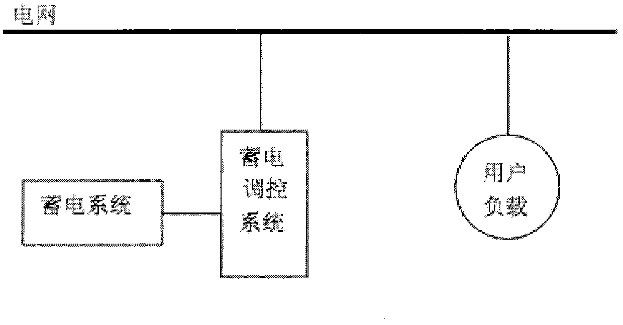
Specifically, if the device realized by this technical solution is used as a grid facility, it will return to the old model of pumped water storage; if it is used as a user device, there are serious defects in grid connection, because the device cannot be supported by the grid. Controlled by the power grid, there will be an island phenomenon, that is, when the power grid is out of power, the power storage system is connected to the grid to supply power to the power grid. Since the power storage system is an island form of power supply that is not controlled by the power grid, it will cause fatal damage to power grid maintenance personnel and equipment. There are huge safety hazards; this technical solution not only has safety hazards, but also the electric energy incorporated into the grid is in a state of no regulation and management. Grid users cannot know whether the grid has been powered off, and the loads of grid users can use the corresponding electric energy. There are hidden dangers of injury and insecurity for users who use electricity. If the power grid is used for metering, allocation and management, the power grid needs to be equipped with a huge management system to ensure the power consumption of power storage users.

Method used


Image

  • User-side peak-shaving power storage and supply system and method
  • User-side peak-shaving power storage and supply system and method
  • User-side peak-shaving power storage and supply system and method

Examples


Embodiment Construction

[0022] As an implementation example, the user-side peak shaving storage power supply system and method are described in conjunction with the accompanying drawings. However, the technology and solutions of the present invention are not limited to the content given in this example.

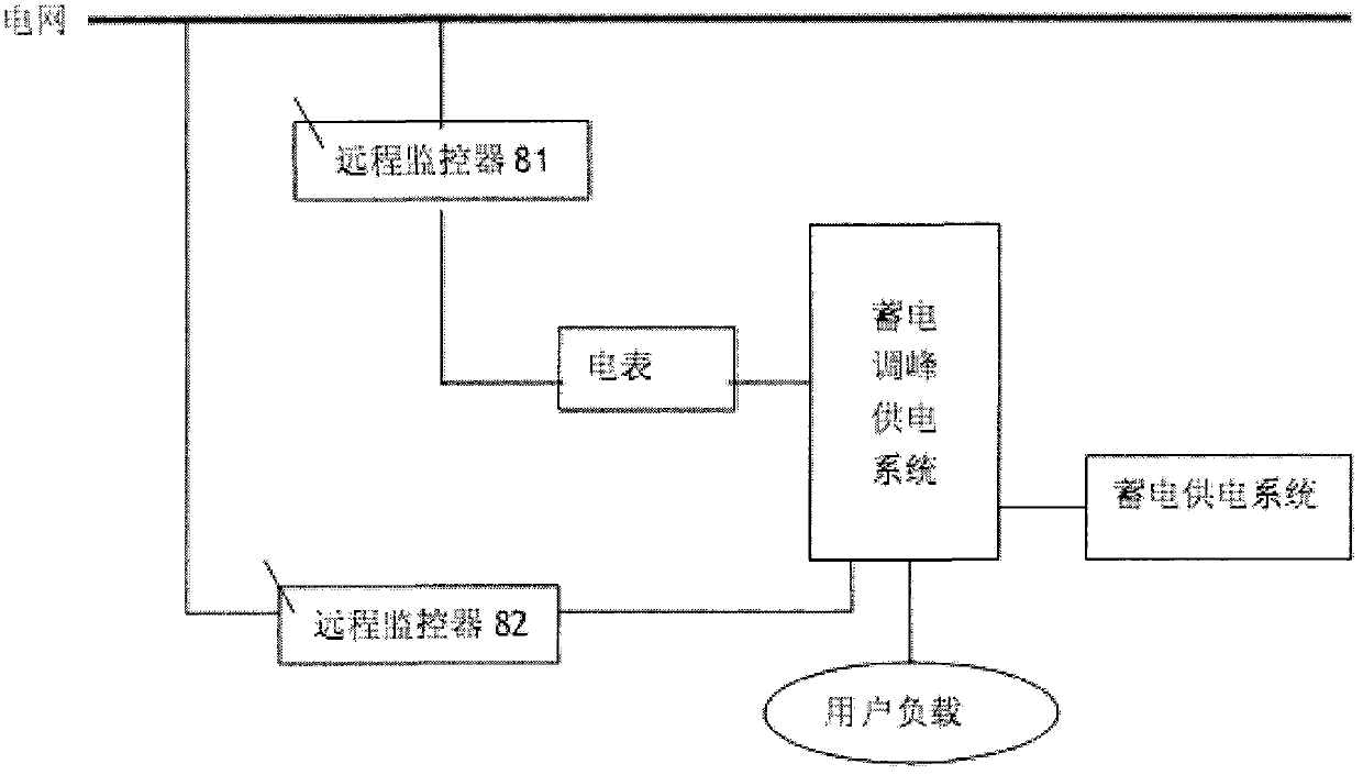
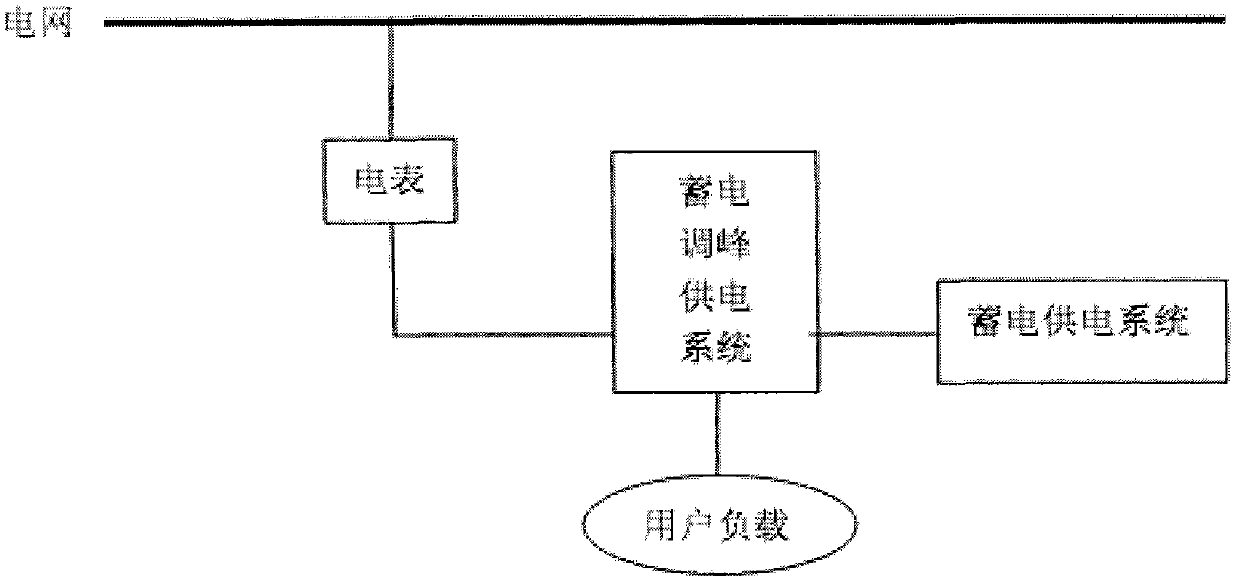
[0023] The specific embodiments of the present invention are described below in conjunction with the drawings. The prior art is essentially a grid-side grid-connected system such as image 3 As shown, for the power grid, this method cannot be controlled by the power grid, and there is a potential safety hazard; the user-side peak-shaving storage power supply system and method proposed in the present invention have two application methods, one of which is the grid-connected method figure 1 As shown, the user-side method is used by the power storage system to directly supply power to the user load with DC and AC electric energy, and part of the electric energy is connected to the grid through the remote mon...


PUM


Abstract

The invention relates to the technical field of power storage and supply, in particular to a user-side peak-shaving power storage and supply system and method. The user-side peak-shaving power storage and supply system is composed of a peak-shaving power supply regulator 1, a monitor 2, an electric control switch 3, a charger 4, an inerter 5, a storage battery pack 6, an input port 7, an output port 8 and a remote monitor 9. The user-side peak-shaving power storage and supply system can be applied in an off-grid manner, is economic and efficient, is convenient to popularize, can also be applied in a grid-connected manner to achieve a complete controlled effect and realize bidirectional monitoring and metering for power supply and power utilization and benign sharing, and has the advantages of being positive and effective as well as environment-friendly and energy-saving for peak shaving of a power grid, reducing occupancy to and wastes of social resources, having no adverse influences to the power grid, realizing grid-connected power supply under a controlled power grid condition, and improving the blackout start capacity of the power grid and the robustness of the power grid.

Description

Technical field [0001] The invention belongs to the technical field of power storage and power supply, and in particular relates to a user-side peak regulation power storage power supply system and method. technical background [0002] 2010-10-27 The Energy Observation Network published an article titled "Smart Grid and Future Energy" and pointed out: "Traditional power grids (or power systems) are powered by a single flow of power generation, transmission, distribution, and consumption. The model, with the production and use of electric energy as the basic goal, is the basis for mass production and consumption of electric power in an industrialized society, as well as a concrete manifestation of the benefits of industrial economies. In power planning and design, more attention should be paid to power load demand and primary Starting from energy production, research and determine the power point, transmission path, transmission capacity and voltage level, and grid structure, etc....

Claims


Application Information

Patent Timeline
Patent Type & Authority Applications(China)
IPC IPC(8): H02J13/00H02J3/28H02J9/00
CPCY04S10/14Y04S20/225Y02B70/3233Y02E60/722Y02B70/30Y02E60/00Y04S20/20
Inventor 周锡卫
Owner IPS TECH LTD
Learn More