CAN (Controller Area Network) branching device

A splitter and transceiver technology, applied in the bus network, data exchange through path configuration, etc., can solve the problems of long delay, complicated programming, etc., and achieve the goals of reducing access, fast response time, and enhancing bus reliability Effect

Inactive Publication Date: 2012-07-18
SHANGHAI STEP ELECTRIC
View PDF2 Cites 6 Cited by
  • Summary
  • Abstract
  • Description
  • Claims
  • Application Information

AI Technical Summary

Problems solved by technology

Most of the existing CAN splitters act on the application layer of the CAN bus. It stores and forwards each frame of data on the CAN bus. The programming is complicated and there is a long delay

Method used


Image

  • CAN (Controller Area Network) branching device
  • CAN (Controller Area Network) branching device
  • CAN (Controller Area Network) branching device

Examples


Embodiment Construction

[0021] The present invention will be further described below in conjunction with the accompanying drawings.

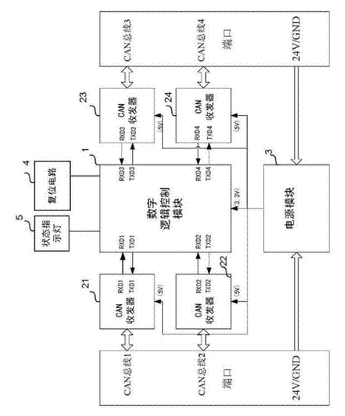
[0022] Please refer to figure 1 . A CAN splitter of the present invention includes a digital logic control module 1 , at least two CAN transceivers, a power supply module 3 , a reset circuit 4 and a status indicator light 5 . figure 1 Only four CAN transceivers 21, 22, 23 and 24 are used as an example, but the number can be flexibly configured according to actual needs, digital logic control module 1 and I / O resources, such as two or three One, five, six, and so on. Each CAN transceiver is connected to one CAN network respectively. exist figure 1 Among them, the CANH end and CANL end of CAN transceiver 21, CAN transceiver 22, CAN transceiver 23 and CAN transceiver 24 are respectively connected to CAN bus 1, CAN bus 2, CAN bus 3 and CAN bus 4.

[0023] The digital logic control module 1 is electrically connected to the transmit data input terminal TXD and the recei...


PUM


Abstract

The invention discloses a CAN (Controller Area Network) branching device which comprises at least two CAN transceivers; a digital logic control module and a power supply model, wherein the at least two CAN transceivers are respectively connected with a path of CAN network; the digital logic control module is respectively and electrically connected with the transmitting data input end and the receiving data output end of each CAN transceiver and is used for sensing a level signal at the receiving data output end of each CAN transceiver, stopping sensing when only one of the CAN transceivers is sensed to be a dominant level signal and transmitting data transmitted by the CAN transceiver to other CAN transceivers, and when the CAN transceiver is changed from the dominant level signal into a recessive level signal, the digital logic control module starts sensing the level signal at the receiving data output end of each CAN transceiver; and the power supply module is used for supplying the power for the digital logic control module and the at least two CAN transceivers. With the adoption of the invention, the quantity of nodes of a CAN bus can be increased, and the communication distance of the CAN bus can be prolonged while a topological structure of the existing CAN bus is not affected.

Description

technical field [0001] The present invention relates to the communication equipment of CAN bus. Background technique [0002] The CAN bus is limited by the topology of the CAN network. When the CAN network nodes reach a certain number or the communication distance reaches a certain value, the CAN nodes cannot be added. When it is necessary to extend the communication distance of the CAN bus and the number of CAN nodes, a CAN splitter is required. Most of the existing CAN splitters act on the application layer of the CAN bus, which stores and forwards each frame of data on the CAN bus, and the programming is relatively complicated and there is a long delay. Contents of the invention [0003] The technical problem to be solved by the present invention is to provide a CAN splitter that acts on the physical layer of the CAN bus, can increase the number of nodes of the CAN bus, and extend the communication distance of the CAN bus without affecting the topology of the original ...

Claims


Application Information

Patent Timeline
Patent Type & Authority Applications(China)
IPC IPC(8): H04L12/40
Inventor 方启宗孙恩涛王武张常青林开伟
Owner SHANGHAI STEP ELECTRIC
Why Eureka
Try Eureka