Method for generating mid-band modulated signal

A technology for modulating signals and bands, which is applied in the field of modulating signals in the mid-band, which can solve the problems of unstable operation of analog circuits, unstable operation of circuits, waste of device costs, etc., and reduce adjacent channel interference, narrow signal frequency band, and out-of-band radiation small effect

Active Publication Date: 2016-06-15
FUJIAN XINGHAI COMM TECH
View PDF3 Cites 0 Cited by
  • Summary
  • Abstract
  • Description
  • Claims
  • Application Information

AI Technical Summary

Problems solved by technology

The implementation of analog circuits has extremely high requirements for the precise selection of component performance. Too small a circuit will work unstable, and too large a circuit will waste device costs and reduce efficiency. On the premise of normal operation, select components with certain margin parameters Devices are more important, and factors such as printed circuit board (PCB) layout and soldering will make the analog circuit unstable

Method used


Image

  • Method for generating mid-band modulated signal
  • Method for generating mid-band modulated signal
  • Method for generating mid-band modulated signal

Examples


Embodiment 1

[0037] Calculate the frequency control word principle according to the frequency synthesizer (the formula is attached in the product manual), Here n=16, the frequency synthesizer 1 input frequency is (T s is a symbol period, and is Set the frequency synthesizer 1 output frequency to 4096KHz. Frequency control word 0 = + frequency control word, frequency control word 1 = - frequency control word. The serial port input symbol 0 selects the frequency control word 0 in the frequency selector, and the symbol 1 selects the frequency control word 1. In the parameter setting of the frequency synthesizer, such as Figure 4 The settings shown: the phase accumulation accuracy is 16; the angular resolution is 12; the magnitude accuracy is 12; the degree of jitter can be selected; the clock rate is 4096kHz; the required output frequency is 1.5kHz; the phase increase value is 24; the actual output frequency is 1.5 kHz. (T s is a symbol period, m is a positive integer; m=1,2,3...)...

Embodiment 2

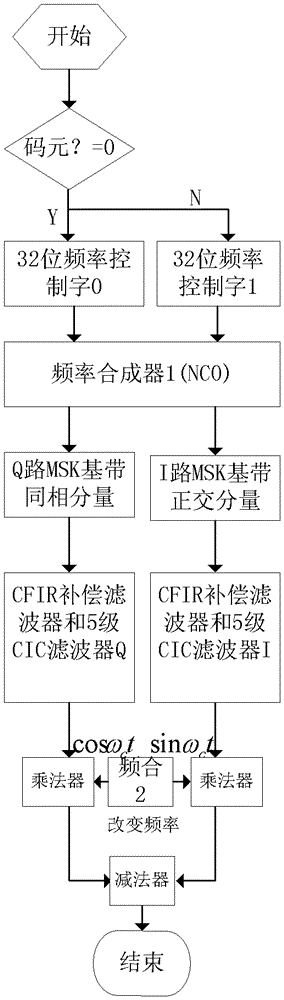
[0040] Calculate the frequency control word principle according to the frequency synthesizer (the formula is attached in the product manual), Here n=32, the frequency synthesizer 1 input frequency is (T s is a symbol period, and is Set the frequency synthesizer 1 output frequency to 4096KHz. Frequency control word 0 = + frequency control word, frequency control word 1 = - frequency control word. The serial port input symbol 0 selects the frequency control word 0 in the frequency selector, and the symbol 1 selects the frequency control word 1. In the parameter setting of the frequency synthesizer, such as Figure 10 Settings shown: (T s is a symbol period, m is a positive integer; m=1,2,3...), when m=5, f c =1.5KHz, that is, the DesiredOutputFrequency item in the figure is 1.5KHz, and the clock item is set to 4096KHz. Check the FrequencyModulationInput item in the Implementation tab, such as Figure 11 Shown: After setting the frequency synthesizer 1 (NCO), click t...


PUM


Abstract

The invention relates to a method of generating a mid-band modulated signal. It comprises frequency control word selector, frequency synthesizer 1, FIR compensation filter and CIC filter I road, FIR compensation filter and CIC filter Q road, frequency synthesizer 2; Described frequency control word selector and frequency synthesis One end of said FIR compensation filter and CIC filter I road and one end of said FIR compensation filter and CIC filter Q road are connected with frequency synthesizer 1 respectively, said FIR compensation filter and CIC The other end of the I path of the filter and the other ends of the Q path of the FIR compensation filter and the CIC filter are connected to the frequency synthesizer 2 . The minimum frequency shift keying modulation signal is applied to the mid-band to reduce the generation of nonlinear products. The minimum frequency shift keying (MSK) modulation signal itself has a relatively concentrated spectrum and a prominent main frequency, which is conducive to improving the channel frequency band utilization and reducing adjacent channel interference.

Description

technical field [0001] The invention relates to a method for generating modulation signals in the mid-wave band. Background technique [0002] At present, the modulation signal generated in the mid-band is realized by means of an analog circuit, that is, a pulse width modulator, such as figure 1 The block diagram of the pulse width modulator is shown. The function of the pulse width modulator is to generate a pulse width modulation signal (SPWM) carrying audio information to drive the modulation power amplifier. [0003] The main principle of pulse width modulation is to use the audio sine wave to modulate the triangular wave to obtain a pulse train with the same amplitude and variable pulse width. The pulse width of this pulse train changes with the audio signal, so it carries audio information. At present, the generation of sine wave is realized by analog circuit. The analog circuit is large in size and slow in speed. As a transmitter signal source generation module, the...

Claims


Application Information

Patent Timeline
Patent Type & Authority Patents(China)
IPC IPC(8): H04L27/12
Inventor 吴桂琴黄奇家郑振端
Owner FUJIAN XINGHAI COMM TECH
Why Eureka
Try Eureka