Method for breaking brittle material substrate

A technology of brittle material substrates and edge materials, applied in the direction of nonlinear optics, stone processing tools, stone processing equipment, etc., can solve the problems that the split surface is easy to break and it is difficult to enhance the strength of the end face, so as to reduce product failure and reduce load , The effect of enhancing the strength of the end face

Inactive Publication Date: 2012-07-18
MITSUBOSHI DIAMOND IND CO LTD
View PDF4 Cites 6 Cited by
  • Summary
  • Abstract
  • Description
  • Claims
  • Application Information

AI Technical Summary

Problems solved by technology

When splitting with a breaking bar, since one scribe line S is split at one time with a large load, the load on the substrate becomes larger, and the split surface tends to be cracked, making it difficult to enhance the strength of the end face.

Method used


Image

  • Method for breaking brittle material substrate
  • Method for breaking brittle material substrate
  • Method for breaking brittle material substrate

Examples


Embodiment Construction

[0045] Hereinafter, details of the breaking method of the present invention according to the present invention will be described in detail with reference to the drawings.

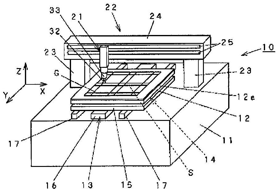
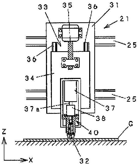
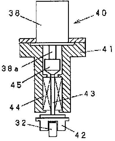
[0046] (fracture device) figure 1 It is a figure which shows the whole structure of the breaking apparatus 10 used when carrying out the breaking method of this invention. A scribing table 12 on which a substrate G is placed is provided on the base 11 . The scribing table 12 includes a Y-axis driving mechanism 13 for moving in the Y direction, and a scribing table rotating mechanism 14 installed below the scribing table 12 to rotate the scribing table 12 . Rubber 12a is laid on the upper surface of the scribing table 12, and when a load is applied to the substrate G from above, the substrate G is easily bent. The Y-axis drive mechanism 13 includes a Y stage 15 that supports the scribe table 12 via a scribe table rotation mechanism 14 , a linear motor 16 that drives the Y stage 15 in the Y direction, and ...


PUM


Abstract

Provided is a breaking method by which an end surface strength can be stronger. A method for breaking a brittle material substrate comprises a step for forming a scribe line on the brittle material substrate, and a breaking step for breaking along the scribe line. In the breaking step, a break roller is pressed on and applies a load to the brittle material substrate placed on a table by rolling the break roller near the scribe line along a position separate from the scribe line to one side, so as to fold at a low load and divide the substrate.

Description

technical field [0001] The present invention relates to a fracture method for singulation along a scribe line formed on a brittle material substrate. Here, the brittle material substrate includes glass, ceramics (low-temperature fired ceramics and high-temperature fired ceramics), semiconductor materials such as silicon, sapphire, and the like. In addition, the form of the substrate to be divided includes not only a single board but also a bonded substrate in which two substrates are bonded together. Background technique [0002] Figure 8 It is a diagram showing an example of a conventional method of dividing a glass substrate on which a functional film such as a panel product has been formed using a breaking bar. First, the substrate G is placed on the scribing table of the scribing device, and the scribing line S is formed along the planned division line of the first surface using the cutter wheel W ( Figure 8 (a)). Next, the substrate G is placed on the elastic scribi...

Claims


Application Information

Patent Timeline
Patent Type & Authority Applications(China)
IPC IPC(8): B28D5/00B28D1/24C03B33/033G02F1/1333
CPCB28D1/222C03B33/076B28D1/24C03B33/027C03B33/033B28D5/00G02F1/1333
Inventor 市川克则
Owner MITSUBOSHI DIAMOND IND CO LTD
Why Eureka
Try Eureka