Ultrasound transducer for using in a fluid medium

一种流体介质、电声换能器的技术,应用在使用声波/超声波/次声波进行材料分析、发声器械、液体/流体固体测量等方向,能够解决费事等问题,达到简化装配和安装的效果

Inactive Publication Date: 2012-07-18
ROBERT BOSCH GMBH
View PDF6 Cites 7 Cited by
  • Summary
  • Abstract
  • Description
  • Claims
  • Application Information

AI Technical Summary

Problems solved by technology

This method is extremely laborious

Method used


Image

  • Ultrasound transducer for using in a fluid medium
  • Ultrasound transducer for using in a fluid medium
  • Ultrasound transducer for using in a fluid medium

Examples


Embodiment Construction

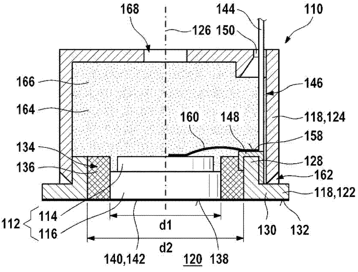
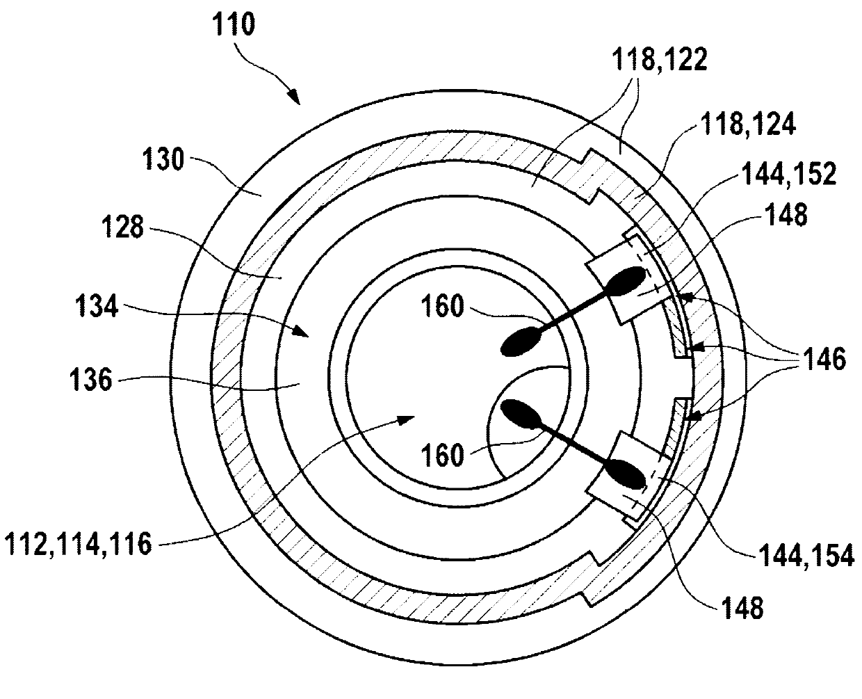
[0033] exist figure 1 and 2 A possible embodiment of an ultrasound transducer 110 according to the invention is shown in . here figure 1 shows a side sectional view, while figure 2 In the direction of the line of sight from above is shown perpendicular to the figure 1 A section view of a section plane. The ultrasonic transducer 110 includes a transducer core 112 which itself includes an electro-acoustic transducer element 114 and a matching body 116 . Here, the matching body 116 is formed, for example, by a λ / 4 impedance matching layer. The electroacoustic transducer element 114 can be formed, for example, from a piezoelectric element and can be connected to the matching body 116 directly or via at least one intermediate layer (for example, an intermediate layer for thermomechanical stress compensation). In the exemplary embodiment shown, matching body 116 has a slightly larger diameter d1 than electroacoustic transducer element 114 . For example, the entire transducer...


PUM


Abstract

The invention relates to an ultrasound transducer (110) for using in a fluid medium (120). The ultrasound transducer (110) comprises at least one transducer core (112) having at least one electric-acoustic transducer element (114). The ultrasound transducer (110) also comprises at least one housing (118) having at least two housing parts (122, 124). At least one first housing part (122) at least partially surrounds the transducer core. A rear side of the electric-acoustic transducer element (114) facing away from the fluid medium (120) is accessible. At least one second housing part (124) is connected to the first housing part (122). The ultrasound transducer (110) is essentially sealed by the second housing part (124), on its side facing away from the fluid medium (120).

Description

Background technique [0001] Ultrasonic transducers in various fields of use are known from the prior art. Ultrasonic transducers are used, for example, in ultrasonic flow meters in automotive technology, for example in the exhaust and / or intake manifold of internal combustion engines. Examples of such ultrasonic transducers are described in DE 10 2007 037 088 A1 or in the later published German patent application DE 10 2008 055 126.0 by the applicant company. Ultrasonic flow meters are often based on two ultrasonic transducers, which are arranged offset in the flow direction in the fluid line and transmit ultrasonic signals to one another. Measuring devices can also be used here, in which at least one reflector is provided, for example in the form of a plug-in sensor. Other applications of ultrasonic transducers are, for example, level gauges or distance gauges, for example in so-called parking guidance systems. [0002] Ultrasonic transducers in many cases have electroacou...

Claims


Application Information

Patent Timeline
Patent Type & Authority Applications(China)
IPC IPC(8): G01F1/66G10K9/22
CPCG10K9/22G01F23/296G01F23/2968G10K9/122G01N29/2437Y10T29/49005
Inventor R・米勒G・许夫特尔M・赫斯特布林克T・朗S・拉德万B・金茨R・万贾
Owner ROBERT BOSCH GMBH
Why Eureka
Try Eureka