

Squirrel-cage Rotor And Method For Producing Such A Squirrel-cage Rotor
A technology for short-circuiting rotors and rotor shafts, which is applied in the manufacture of squirrel-cage rotors, motor generators, electrical components, etc. The effect of balancing and breaking
- Summary
- Abstract
- Description
- Claims
- Application Information
AI Technical Summary
Problems solved by technology
Method used
Image

Examples
Embodiment Construction
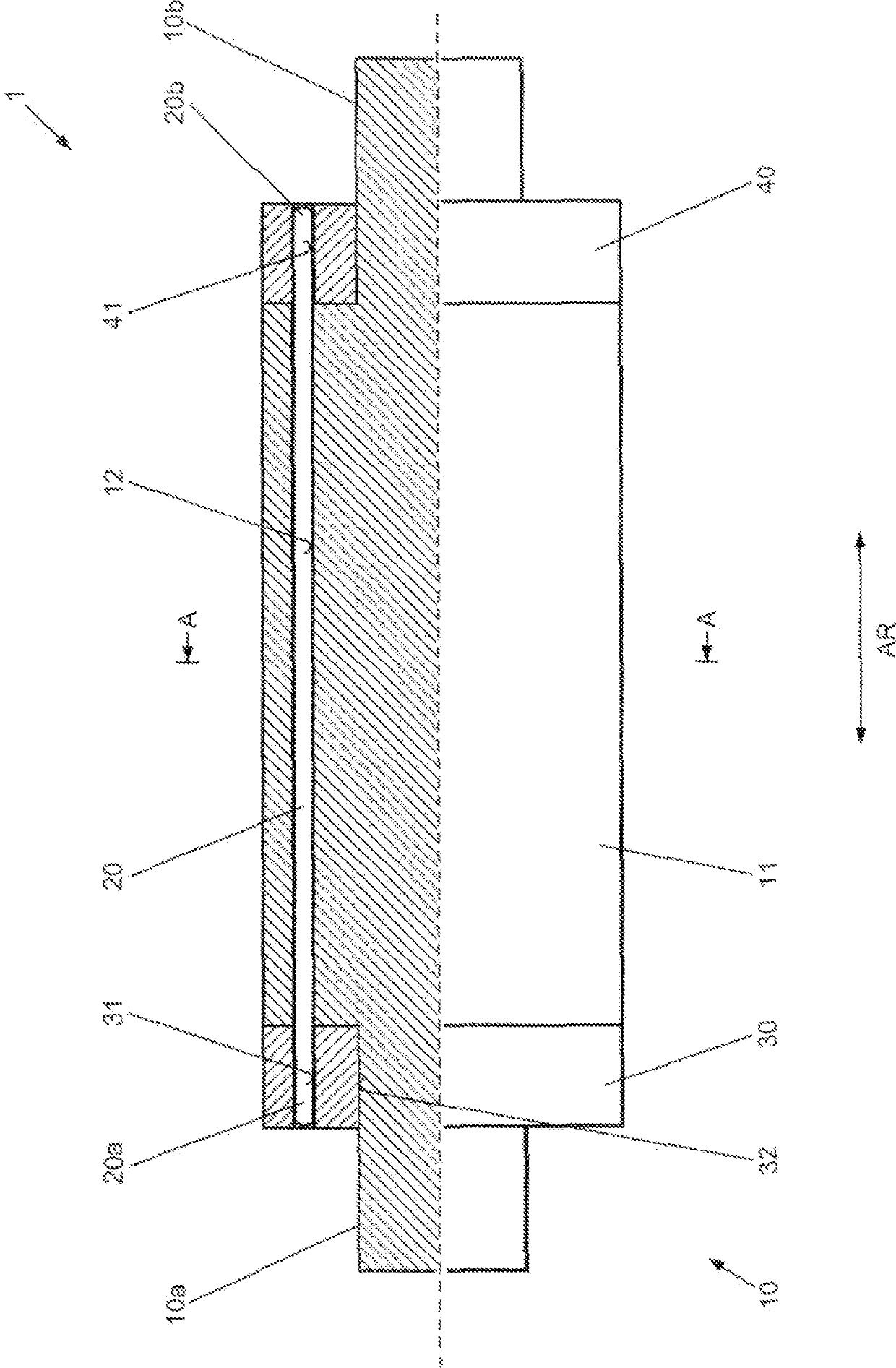
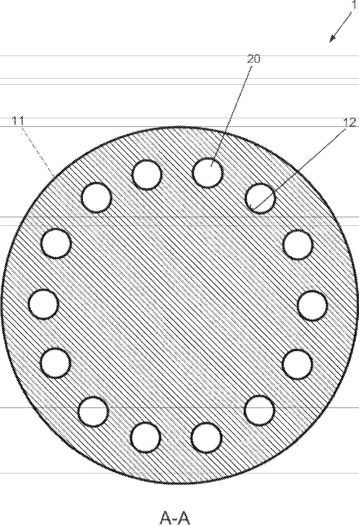
[0041] as in figure 1 and figure 2 As shown in , a short-circuit rotor 1 (not shown in full) for an electric motor according to the invention has a rotor shaft 10 formed of ferromagnetic material (which has a cylindrical shaft molded thereon in one piece). A solid rotor section 11 in the form of a diameter enlargement (Durchmesservergroesserung), a plurality of electrically conductive rod elements 20 (which have an annular cross-section with a constant diameter) and in the form of two corresponding one-piece end rings Two electrically conductive end elements 30 and 40 .
[0042] The solid rotor section 11 has a plurality of through-channels 12 extending distributed around the circumference of the rotor shaft 11 in the axial direction AR of the rotor shaft 10 .
[0043] A rod element 20 is accommodated in each of the through channels 12 such that the respective rod element 20 extends through the solid rotor section 11 in the axial direction AR of the rotor shaft 10 , wherein...
PUM
 Abstract
Description
Claims
Application Information