Motor casing with spiral airflow chamber

A technology of spiral airflow and motor casing, applied in the direction of casing/cover/support, electrical components, electromechanical devices, etc., can solve the problems of loud noise, user discomfort, poor effect, etc., to reduce noise and extend the flow path , the effect of reducing noise

Inactive Publication Date: 2012-07-25
LG ELECTRONICS (TIANJIN) APPLIANCES CO LTD
View PDF2 Cites 1 Cited by
  • Summary
  • Abstract
  • Description
  • Claims
  • Application Information

AI Technical Summary

Problems solved by technology

There are sound-absorbing partitions or sound-absorbing sponges installed in the air duct around the motor, but the effect is poor, and the motor is still running with a lot of noise, which makes users feel very uncomfortable

Method used


Image

  • Motor casing with spiral airflow chamber
  • Motor casing with spiral airflow chamber
  • Motor casing with spiral airflow chamber

Examples


Embodiment Construction

[0029] The present invention will be further described in detail below in combination with specific embodiments.

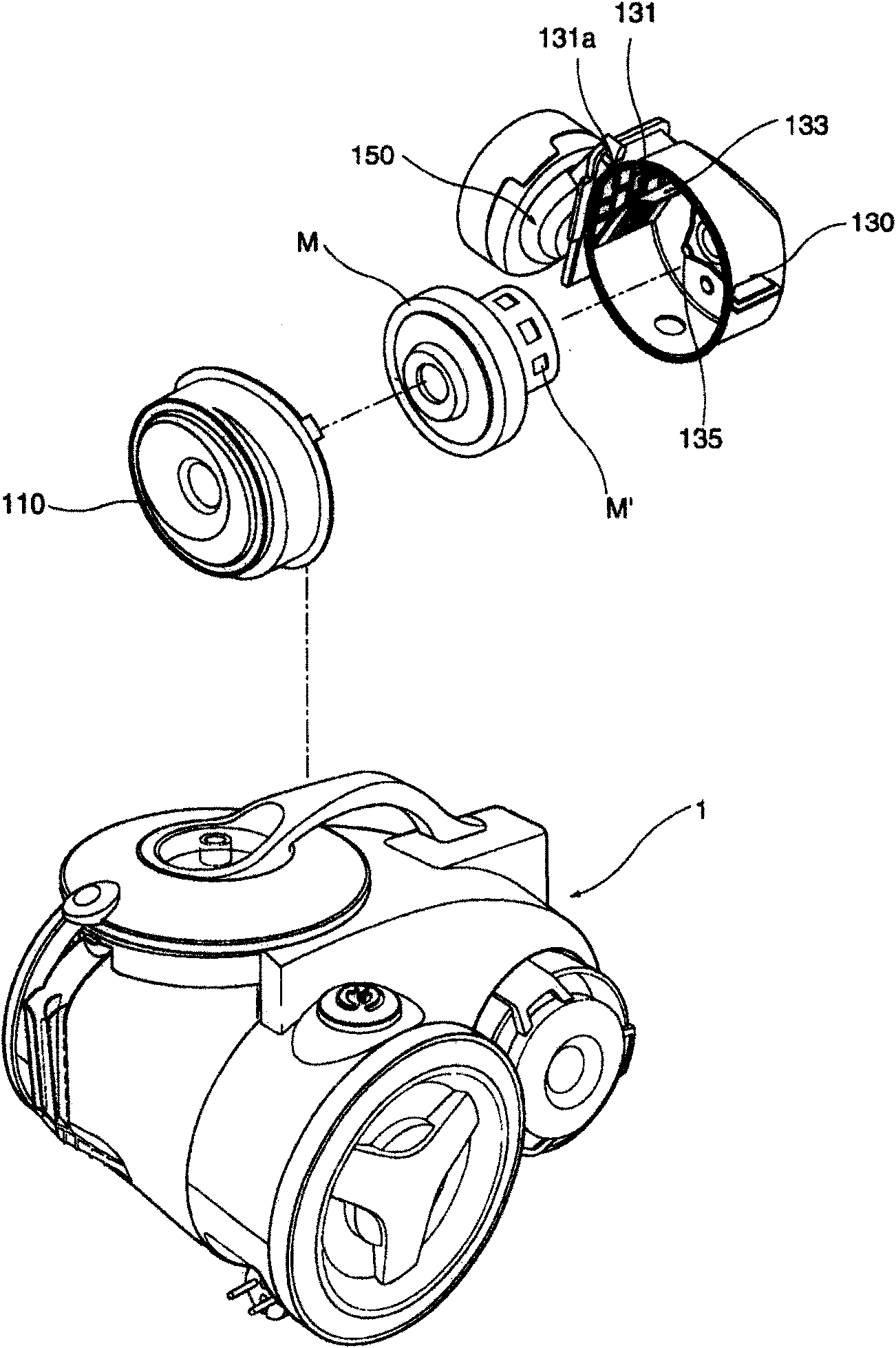
[0030] Such as Figure 4-2 with Figure 4-4 As shown, the present invention has a motor casing with a spiral air flow chamber, including a cavity, an air inlet 11 and an air outlet 12, the air inlet 11 is located at the bottom of the cavity, and the air outlet 12 is located at the bottom of the cavity side of the body; Figure 4-5 As shown, a partition is provided in the cavity, and the partition is formed by alternately connecting flat plates and curved panels, and the curved panel is a curved panel that is substantially equidistant from the outer wall of the cavity, such as Figure 4-5As shown, the curved plate is a circular arc plate, and alternately arranged and connected expansion chambers 20 and contraction chambers 10 are formed between the partition plate and the outer wall of the cavity, and are aligned with the air outlet 12 A grid-shaped air port is ...


PUM


Abstract

The invention discloses a motor casing with a spiral airflow chamber, which comprises a chamber body, an air inlet and an air outlet. The air inlet is located at the bottom of the chamber body, and the air outlet is located on the lateral surface of the chamber body. The chamber body is provided with a baffle plate which is formed by a panel and a curved plate connected alternately. An expansion chamber and a contraction chamber which are communicated and arranged alternately are arranged between the baffle plate and the outer wall of the chamber body. A grid-shaped air hole is arranged at a position opposite to the air outlet. A flow channel of spiral air-out passing through the air inlet, the alternated expansion chamber and contraction chamber and the air outlet sequentially. The motor casing is provided with a longer spiral flow channel. The flow resistance of the spiral flow channel is smaller, so that the motor casing provided is further beneficial for improving the overall efficiency of the dust collector and reducing the noise. And the alternate expansion chamber and contraction chamber are arranged in the spiral flow channel so as to increase the loss of sound energy.

Description

technical field [0001] The invention relates to a motor casing, in particular to a spiral airflow motor casing. Background technique [0002] Vacuum cleaners are commonly used household appliances for cleaning rooms or objects. Its working principle is: through the internal fan motor to generate strong suction, the dust and foreign objects on the floor or in the crevices are sucked into the vacuum cleaner together with the air, and filtered Then the air is discharged, and the dust and foreign matter are collected in the dust collection device. Such as figure 1 As shown, the existing common vacuum cleaner includes a body 100, an extension pipe 300, a suction pipe 200 and a suction nozzle 400. The inside of the body 100 is provided with a fan motor M (not shown in the figure), and the fan motor M is used to generate suction , the dust and foreign objects are sucked into the main body 100 through the suction pipe 200 , the extension pipe 300 and the suction nozzle 400 . The ...

Claims


Application Information

Patent Timeline
Patent Type & Authority Applications(China)
IPC IPC(8): A47L9/00H02K5/04H02K5/24
Inventor 武甜甜
Owner LG ELECTRONICS (TIANJIN) APPLIANCES CO LTD
Why Eureka
Try Eureka