Position changing transmission mechanism of automatic tool changing device

A technology of automatic tool change and transmission mechanism, applied in positioning devices, metal processing machinery parts, clamping, etc., can solve problems such as maintenance costs that cannot be ignored, high price, difficult processing of arc-shaped indexing cams, etc., and achieve simple structure , low cost, easy to manufacture

Inactive Publication Date: 2012-07-25
HUBEI UNIV OF AUTOMOTIVE TECH
View PDF7 Cites 6 Cited by
  • Summary
  • Abstract
  • Description
  • Claims
  • Application Information

AI Technical Summary

Problems solved by technology

[0004] The tool change is realized through the arc indexing cam as the main body. The machining of the arc indexing cam is difficult, the price is expensive, and the follow-up maintenance cost cannot be ignored.

Method used


Image

  • Position changing transmission mechanism of automatic tool changing device
  • Position changing transmission mechanism of automatic tool changing device
  • Position changing transmission mechanism of automatic tool changing device

Examples


Embodiment Construction

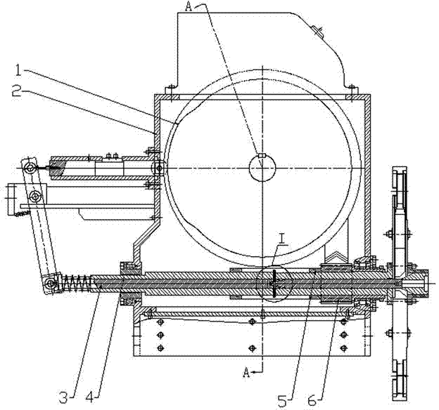
[0014] The transposition transmission mechanism of the automatic tool changer is composed of a tool transposition part and a transmission clutch part.

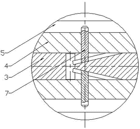
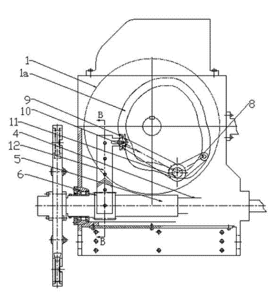
[0015] Such as figure 1 , 3 , 4, the structure of the tool transposition part: it is mainly composed of a transposition swing rod 10, a shift fork 9, a transmission gear 6, a rack 12, and a rolling guide pair (composed of a guide rail 13 and two sliders 14). The bar 12 is supported on the inner wall of the box body 2 by the rolling guide pair, the middle part of the transposition swing rod 10 is hinged on the box body 2, and one end of the transposition swing rod is connected with the rack 12 through the shift fork 9; On the main shaft 4 of the knife arm, the transmission gear 6 meshes with the rack 12; the other end of the transposition swing rod 10 is fixed with a bearing 8, and the compound cam 1 is connected with the other end of the transposition swing rod through the bearing 8, and the bearing of the transposition swing...


PUM


Abstract

The invention provides a position changing transmission mechanism of an automatic tool changing device, which comprises a tool position changing portion and a transmission clutch portion. The technical scheme includes that the tool position changing portion is meshed with a transmission gear hollowly sleeved on a tool arm spindle via a rack mechanism, the rack mechanism is in movement linkage with a composite cam, the transmission clutch portion structurally includes that one side of a spindle sleeve hollowly sleeved on the tool arm spindle is fixedly connected with the transmission gear, a T-shaped groove is machined in the middle of a push rod of a tool locking mechanism, a certain angle is formed between the bottom of the T-shaped groove and the axis of the push rod, a T-shaped pin is mounted in the T-shaped groove and inserted into a tool arm spindle positioning hole, and a corresponding axial groove is arranged on the spindle sleeve. The gear and rack mechanism is combined with the composite cam, movement forms are converted, whether the tool arm spindle rotates or not is controlled by the transmission clutch portion, accordingly, tool position change is controlled, a tool position change mode adopting an arc-surface indexing cam as a main transmission body is completely replaced, and the position changing transmission mechanism has the advantages of simple structure, convenience in manufacture and low cost.

Description

technical field [0001] The invention relates to an automatic tool changing device of a high-speed machining center, especially its transposition transmission mechanism. Background technique [0002] A current automatic tool changing device for a high-speed machining center includes a box body, a tool arm spindle, a tool changing arm, a power transmission mechanism, a tool inserting mechanism, a tool changing mechanism, and a tool locking mechanism. The tool arm spindle is supported by a bearing on the The box body and the main shaft of the knife arm can reciprocate axially, and the tool changing arm is fixed on the front end of the main shaft of the knife arm; the structure of the power transmission mechanism: it is mainly composed of a motor, a reducer, multiple gears, and a compound cam, and the motor is connected to the reducer , the reducer transmits power to the compound cam through multiple gears, the compound cam is supported on the box through the rotating shaft, the...

Claims


Application Information

Patent Timeline
Patent Type & Authority Applications(China)
IPC IPC(8): B23Q3/155
Inventor 邱新桥杨威
Owner HUBEI UNIV OF AUTOMOTIVE TECH
Why Eureka
Try Eureka