Micro flapping rotor aircraft

A technology of fluttering rotors and aircraft, applied to aircraft, helicopters, motor vehicles, etc., can solve the problems of reducing upward lift, increasing mass, and large rotational thrust

Inactive Publication Date: 2012-07-25
NORTHWESTERN POLYTECHNICAL UNIV
View PDF7 Cites 16 Cited by
  • Summary
  • Abstract
  • Description
  • Claims
  • Application Information

AI Technical Summary

Problems solved by technology

This "W" or "3W" shaped electromagnetic drive mechanism needs to be provided with a U-shaped soft iron sheet, a magnetically closed iron sheet and a spring under each flapping wing, causing the mechanism to be repeated and the quality to be doubled; this whole electromagnetic drive The mechanism rotates around the central axis of the aircraft, which requires a large rotational thrust generated by flapping wings, which reduces the upward lift
However, this invention creates repetitive mechanisms, and the electromagnetic drive mechanism rotates around the central axis of the aircraft, which has the disadvantages of large rotational thrust and small upward lift force generated by the fluttering of the required flapping wings.

Method used


Image

  • Micro flapping rotor aircraft
  • Micro flapping rotor aircraft
  • Micro flapping rotor aircraft

Examples


Embodiment Construction

[0022] The present invention will be further described below in conjunction with the accompanying drawings and implementation examples.

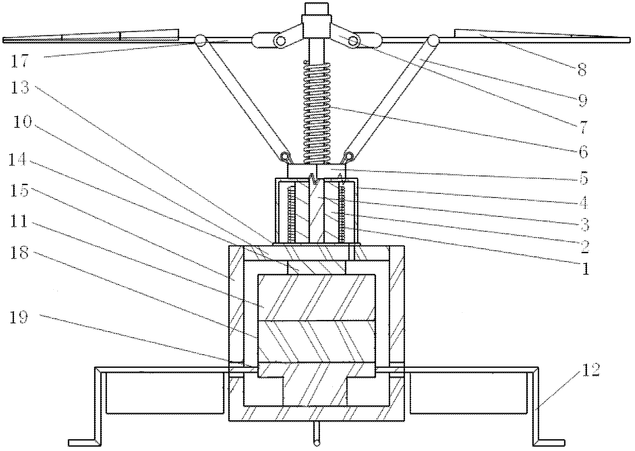
[0023] as attached figure 1 shown. This embodiment is a miniature flapping rotor aircraft, comprising an electromagnetic driver, an operating sleeve 5, a spring 6, a suspension joint 7, a flapping wing 8, a connecting rod 9, a support platform 10, a battery 11, an undercarriage 12, a controller 14, Body shell 15, control surface 16, receiver 18 and steering gear 19.

[0024] The suspension joint 7 is set on the top of the longitudinal keel 3 of the body; the connecting rods of the two flapping wings 8 are respectively hinged with the connecting lugs on the outer circumference of the suspension joint 7; the two flapping wings 8 are symmetrically installed on the suspension joint 7, and The layout mode is the same as the helicopter blade layout mode, and the directions of the trailing edges of the two flapping wings 8 are opposite. The spri...


PUM


Abstract

The invention relates to a micro flapping rotor aircraft. A suspension joint is sleeved at the top end of a vertical keel of an aircraft body. Connecting rods of two flapping wings are respectively hinged with connecting lugs on the outer circumference of the suspension joint. The two flapping wings are installed symmetrically on the suspension joint and the rear edges of the flapping wings are in the opposite directions. A spring is sleeved on the vertical keel of the aircraft body and located below the suspension joint. An actuating cover is sleeved on the vertical keel of the aircraft body and located below the spring. One ends of the connecting rods are connected with the flapping wings through hinge joints while the other ends of the connecting rods are connected with the actuating cover through hinge joints. An electromagnetic driver is sleeved on the vertical keel of the aircraft body and located below the actuating cover. A control surface is bonded to a support arm of an undercarriage. A differential control surface and a synchronous control surface fixed on the undercarriage are distributed alternately. The magnet in the invention does not need to rotate around the center of the aircraft, so that thrust required to rotate flapping wings around the vertical keel of the aircraft body is reduced so as to improve the lifting force. And the micro flapping rotor aircraft is simple in structure and light in weight.

Description

technical field [0001] The design of the invention belongs to the technical field of micro-aircraft, in particular to a micro-flapping-rotor aircraft. Background technique [0002] In the invention with the application number 200910079817.1, a method for designing a flapping rotor and a miniature flapping rotor aircraft designed using this method are proposed. The electromagnetic drive mechanism of the micro-flapping rotor aircraft proposed by this invention adopts a "W" shape or "3W" shape, and U-shaped soft irons are juxtaposed together, with magnetically closed iron sheets sandwiched in the middle, and wires are wound on the outer surface to form a "W" shape. . One end of two magnetically closed iron sheets is fixed between two U-shaped soft irons, the bottom end of the iron sheet is glued to the connecting shaft, and the other end is fixed or glued to the root of the flapping wing; the two springs are respectively fixed on the "W On both sides of the "shaped electromag...

Claims


Application Information

Patent Timeline
Patent Type & Authority Applications(China)
IPC IPC(8): B64C33/00
Inventor 李占科裘志杰彭中良徐合良张翔宇
Owner NORTHWESTERN POLYTECHNICAL UNIV
Why Eureka
Try Eureka