
Method for calibrating the pivoting path of a yarn regulator and a yarn piecing device

A technology of a piecing device and a regulator, which can be used in spinning machines, transportation and packaging, open-end spinning machines, etc., and can solve problems such as high manufacturing costs

Active Publication Date: 2016-03-02
RIETER AUTOMATIC WINDER GMBH
View PDF7 Cites 0 Cited by
  • Summary
  • Abstract
  • Description
  • Claims
  • Application Information

AI Technical Summary

Problems solved by technology

Although damage to the yarn regulator and its supporting device can be largely avoided by using such an angle of rotation sensor, such a yarn piecing device cannot be implemented in practice, especially because of its relatively high manufacturing costs.

Method used


Image

  • Method for calibrating the pivoting path of a yarn regulator and a yarn piecing device
  • Method for calibrating the pivoting path of a yarn regulator and a yarn piecing device
  • Method for calibrating the pivoting path of a yarn regulator and a yarn piecing device

Examples


Embodiment Construction

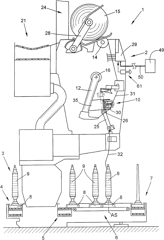
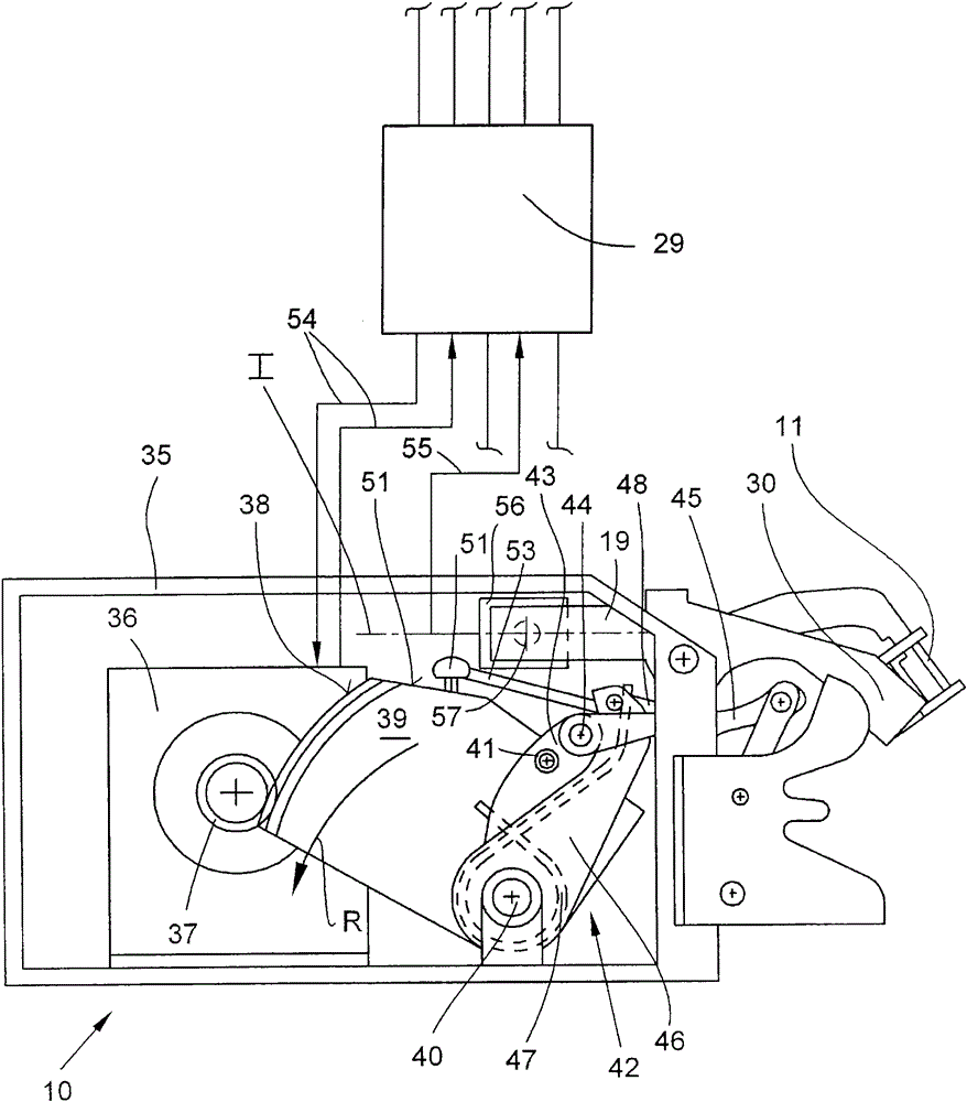
[0041] figure 1 A textile machine, designated as a whole with the reference numeral 2 , for producing cross-wound bobbins, which in this exemplary embodiment is an automatic cross-winder 1 , is schematically shown in side view. This automatic cross-winder 1 has between its end frames (not shown) a number of stations 2 of the same type on which the textile bobbins, preferably produced on the ring spinning machine, will be 9 The cross-wound bobbin 15 rewound into a large package, after the cross-wound bobbin 15 has been produced, is handed over to the cross-wound bobbin arranged in the longitudinal direction of the machine by means of an automatically working service unit (also not shown) Package transfer device 21.

[0042] Furthermore, such an automatic crosswinder 1 often has a conveying device, for example in the form of a cop and bobbin conveying system 3, in which the figure 1 Only the bobbin supply area 4, the reversibly drivable storage area 5, the transverse transport...


PUM


Abstract

The method involves counting number of working steps executed by a stepper motor during swivel process, and comparing the number of working steps that are determined as a guidance value. A correction factor is created based on the comparison. An exact positioning of a thread feeder (30) in a predeterminable operative position is guaranteed in course of splice processes during regular spooling necessary swiveling operations. The correction factor is considered during the swivel process. The thread feeder is more displaceable by the stepping motor. An independent claim is also included for a thread splicing apparatus for adjusting a swivel path of a thread feeder.

Description

technical field [0001] The invention relates to a method for calibrating the pivoting path of a yarn regulator provided on a yarn piecing device of a textile machine for producing cross-wound bobbins, and to a corresponding Yarn piecing device. Background technique [0002] In the textile industry, especially in connection with automatic cross-winders, a yarn piecing device has been known for a long time, which has a yarn regulator for positioning two yarn ends in the splicing channel of the splicing prism, and This is described in detail in a large number of patent documents. [0003] With the aid of such a yarn piecing device, two yarn ends can be swirled pneumatically into a knot-free connection, ie, ideally, this connection has almost the strength of the yarn and has almost the same appearance as the yarn. This means that in the event of a yarn break during the winding process at one of the stations of the automatic cross-winder or a defined clearer cut, special pneuma...

Claims


Application Information

Patent Timeline
Patent Type & Authority Patents(China)
IPC IPC(8): B65H69/06D01H4/42
CPCB65H69/061B65H2701/31
Inventor 赫尔穆特·科伦O·内比格S·斯查顿彼得·施瓦兹
Owner RIETER AUTOMATIC WINDER GMBH
Learn More