Prestressed concrete supporting pile wall

A technology for supporting pile walls and concrete, applied in sheet pile walls, construction, excavation, etc., can solve the problems of large amount of steel bars and concrete in cast-in-situ piles, high transportation and leasing costs of section steel, and increased use cost of section steel, etc., to achieve Good economic benefits, enhanced bending stiffness and lateral movement resistance, and reduced transportation costs

Active Publication Date: 2012-07-25
JIANGSU DINGDA BUILDING NEW TECH +1
View PDF8 Cites 5 Cited by
  • Summary
  • Abstract
  • Description
  • Claims
  • Application Information

AI Technical Summary

Problems solved by technology

[0004] However, SMW construction method piles have the following disadvantages: H-shaped steel is mostly used in SMW construction method piles, and the cost of H-shaped steel is high. In the actual construction process, the transportation cost and leasing cost of the section steel are very high, especially when the construction period is long. , the rental cost of section steel will greatly increase the cost of use
In addition, the section steel generally needs to be pulled out after the construction of the basement is completed, which may lead to the loss of the section steel such as bending and breaking, and will greatly increase the project cost when the site limit cannot be pulled out.
[0005] Cast-in-situ piles use a lot of steel bars and concrete, and additional water-stop curtains need to be installed. The construction is cumbersome and has a relatively large impact on the environment.
[0006] Therefore, the supporting structure used in the existing building foundation pit engineering can not fully meet the engineering needs, and it is necessary to develop a new type of foundation pit supporting structure, which is safe, reliable, economical and reasonable, and convenient for construction.

Method used


Image

  • Prestressed concrete supporting pile wall
  • Prestressed concrete supporting pile wall
  • Prestressed concrete supporting pile wall

Examples


Embodiment Construction

[0033] The preferred embodiments of the present invention will be described in detail below in conjunction with the accompanying drawings, so that the advantages and features of the present invention can be more easily understood by those skilled in the art, so as to define the protection scope of the present invention more clearly.

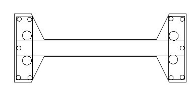
[0034] see Figure 1 to Figure 4 , the embodiment of the present invention includes:

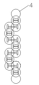
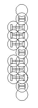
[0035] A prestressed concrete supporting pile wall, comprising: a cement-soil wall composed of several cement-soil mixing piles 4, the cement-soil wall has a convex or staggered structure, and the cement-soil mixing pile 4 is continuous Or prefabricated piles are inserted at intervals.

[0036] The cement-soil mixing pile 4 is constructed by a three-axis cement-soil mixing pile construction machine, and three cement-soil mixing piles 4 interlocking are processed each time, which are respectively the front pile, the middle pile and the rear pile, forming a ceme...


PUM


Abstract

The invention discloses a prestressed concrete supporting pile wall, which comprises a cement-soil wall consisting of a plurality of cement-soil stirring piles. The cement-soil wall is provided with an outwards protruded or staggered structure, prefabricated piles are continuously or intermittently inserted in the cement-soil stirring piles, each prefabricated pile comprises multiple sections of reinforced concrete members, a plurality of through holes are arranged on each reinforced concrete member along an axis direction, the reinforced concrete members of each prefabricated pile are serially connected together via an anti-bending rope penetrating through the through holes of the prefabricated pile, after being tensioned, each anti-bending rope is respectively fixedly connected with two ends of the corresponding prefabricated pile, and a reinforcing anti-shear plate is fixedly mounted at a joint of each two adjacent reinforced concrete members. Due to the mode, the prestressed concrete supporting pile wall not only guarantees safety and reliability of a foundation pit supporting structure, but also has a good economic benefit, is convenient in construction and low in influence to environments, and further meets requirements of foundation pit engineering construction.

Description

technical field [0001] The invention relates to all construction engineering fields such as construction, municipal administration, transportation, water conservancy, electric power, industry, etc., and particularly relates to a prestressed concrete supporting pile wall. Background technique [0002] The technical scheme of foundation pit engineering is mainly considered from the aspects of safety reliability, economic rationality, construction difficulty and construction period. There are many applications of SMW construction method piles, cast-in-place piles and underground diaphragm walls in soft soil areas around the coast of my country. [0003] The steel-cement-soil mixing wall, commonly referred to as the SMW construction method, is a composite soil-retaining and water-proof structure formed by inserting section steel into continuously socketed three-axis cement-soil mixing piles. That is to use the three-axis mixing pile drilling rig to cut the soil in the original ...

Claims


Application Information

Patent Timeline
Patent Type & Authority Applications(China)
IPC IPC(8): E02D5/20E02D17/04
Inventor 徐汉东
Owner JIANGSU DINGDA BUILDING NEW TECH
Why Eureka
Try Eureka