Ceramic solar hot water tile

A solar water heating and ceramic technology, applied in roof drainage, renewable energy integration, roofing using tile/slate tile, etc. problems, to achieve the effect of reducing the overall cost, reducing weight, and good overall decoration

Inactive Publication Date: 2012-07-25
WUXI HEJIAHUAN LOW CARBON TECH
View PDF7 Cites 2 Cited by
  • Summary
  • Abstract
  • Description
  • Claims
  • Application Information

AI Technical Summary

Problems solved by technology

Due to the vertical and smooth surface around the structure of the ceramic heat collecting plate, it is easy to leak when spliced ​​and combined with each other, so it cannot be directly used as a roof tile.
The large area of ​​the roof not only increases the load-bearing capacity of the building roof; but also destroys the design style and decorative effect of the building roof

Method used


Image

  • Ceramic solar hot water tile
  • Ceramic solar hot water tile
  • Ceramic solar hot water tile

Examples


Embodiment 1

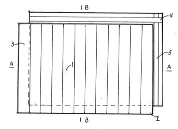
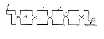
[0015] Embodiment 1: see Figure 1-3 , the ceramic solar water heating tile of the present invention is the same as the prior art. It is made of pottery clay and processed into grouting mud. Using ceramic mold injection molding, it is grouted once to form a hollow cube 1 with corrugated plates on the front and back, and the wave crest is 1.1 and The trough 1.2 (straight rainwater drainage groove) is opposite to each other ( figure 2 This structure is conducive to improving the structural strength of the ceramic hot water tile and reducing deformation during firing, and an air insulation layer is formed between the hot water tile and the roof), the hollow between the two wave plates is the water storage cavity 6, and the wave trough is 1.2 The two ends are slightly shallow, so that the water storage chambers formed by the wave crests are connected. On the sides of the hollow cube, along the upper and adjacent sides in the direction of the trough, the lower part of the thickne...

Embodiment 2

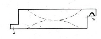
[0016] Example 2: see Figure 4 , as in Example 1, wherein heat-absorbing functional materials such as vanadium tailings or metal oxides are added to the ceramic mud to become ceramic mud with heat-absorbing function. There are two types of hot water tiles 7 and 8 for grouting molding, wherein 7 is a bottom tile structure, and the lower part of the thickness of the adjacent three sides of the peripheral side has a drainage groove 10 protruding outwards (only two sides are shown in the figure). The other side has an outwardly protruding covering edge (not shown in the figure) on the upper part of the thickness; Only two sides are shown), and the lower part of the thickness of the other side has a drainage groove protruding outward. The front of the hot water tile is a corrugated surface with drainage troughs 7.2 and 8.2 respectively, and the bottom surface is a flat bottom plate.


PUM


Abstract

The invention relates to an improvement on a ceramic solar heat absorbing plate for a roof. Ceramic solar hot water tiles are characterized in that lap-joint tiling edges similar to cover tiles and horizontal and vertical grooves similar to concave tiles and used for diverting and draining rainwater are respectively arranged on the side surfaces of a hollow rectangular ceramic body, the lap-joint tiling edges and the horizontal and vertical grooves are adjacent to each other are in lap-joint in the horizontal direction and in the vertical direction, so that the roof tiling type solar hot water tiles can be formed. Each solar hot water tile is provided with not only a horizontal water draining groove but also a longitudinal water draining groove, the front and the back parts and the left and the right parts are assembled and in lap-joint adjacently so as to form a structure similar to a tile, so that water flows smoothly, and the solar hot water tile has the function of rainwater draining, can replace roof tile for being paved on a large-area slope roof, not only can absorb solar energy to generating hot water, but also can be used as the roof tile, can be used as not only a roof solar hot water panel but also the roof tile, has two functions, is good in whole decoration, and is a roof when being seen in a long distance, so that the whole construction cost is lowered, and the roof weight is reduced.

Description

technical field [0001] The present invention is an improvement to the ceramic solar water heating panel for roofing, especially relates to a ceramic solar water heating tile having the function of building roof tiles at the same time, so that building tiles can be omitted while laying the solar water heating panel on the roof, and the roof decoration is good . Background technique [0002] Chinese patent CN201599975U solar ceramic heat-absorbing plate discloses a hollow solar energy ceramic heat-absorbing plate laid on the roof, the surface layer has a corrugated structure, and is respectively provided with a water inlet and a water outlet. Due to the vertical and smooth surface around the structure of the ceramic heat collecting plate, it is easy to leak when spliced ​​together, so it cannot be directly used as a roof tile. . The large area of ​​the roof not only increases the bearing capacity of the building roof; but also destroys the design style and decorative effect ...

Claims


Application Information

Patent Timeline
Patent Type & Authority Applications(China)
IPC IPC(8): E04D13/18E04D13/04
CPCY02B10/20
Inventor 韩顺良刘伟
Owner WUXI HEJIAHUAN LOW CARBON TECH
Why Eureka
Try Eureka