Vacuum generator

A vacuum generator and vacuum technology, applied in machines/engines, non-displacement pumps, mechanical equipment, etc., can solve the problems of large volume, heavy weight, and high energy consumption, and achieve small volume, light weight, and environmental adaptability strong effect

Active Publication Date: 2012-07-25
王伟光
View PDF3 Cites 9 Cited by
  • Summary
  • Abstract
  • Description
  • Claims
  • Application Information

AI Technical Summary

Problems solved by technology

[0003] Traditional vacuum pumps are driven by motors, which generate high energy consumption, are bulky, heavy, and require regular maintenance

Method used


Image

  • Vacuum generator
  • Vacuum generator
  • Vacuum generator

Examples


Embodiment Construction

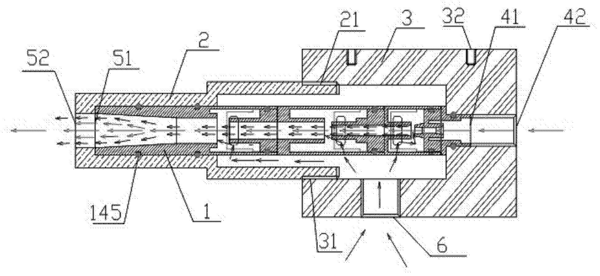
[0026] A vacuum generator provided by the present invention uses compressed air as power, utilizes Bernoulli's principle, takes away the air around the vacuum generating sleeve, and generates vacuum.

[0027] figure 1 It is a schematic cross-sectional view of a vacuum generator with a vacuum generating sleeve. like figure 1 As shown, the vacuum generator includes a vacuum generating sleeve 1 , a sleeve housing 2 and a vacuum generator base 3 .

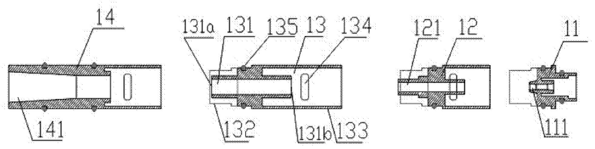
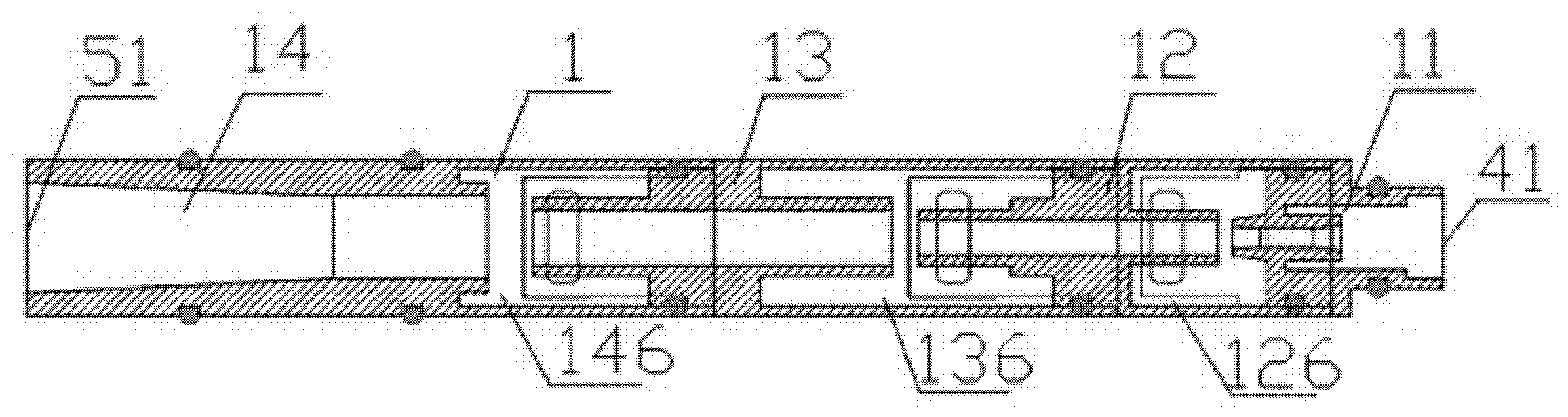
[0028] figure 2 It is a sectional disassembled view of several vacuum generating sleeve parts of the present invention. The vacuum generating sleeve of the present invention is made up of one or more sleeve parts, such as figure 2 The illustrated vacuum generating sleeve includes sleeve parts 11-14, but the number of sleeve parts is not limited thereto. The center position of each sleeve part has a nozzle 111, 121, 131 and 141 (hereinafter represented by 111-141) with different diameters, and the nozzle 111-141 is a through hole...


PUM


Abstract

The invention provides a vacuum generator which is characterized in that air around a vacuum generation sleeve is taken away to generate vacuum by adopting compressed air as power and utilizing a Bernoulli principle. The vacuum generator comprises the vacuum generation sleeve, a sleeve shell and a vacuum generator base. The compressed air enters from a compressed air inlet of the base and drives the air in the vacuum generation sleeve to flow in the axial direction, so that the air pressure outside the sleeve is larger than that inside the sleeve; and the air outside flows into the sleeve through a through hole on the side wall of the sleeve and then flows out from a compressed air outlet of the sleeve (or the sleeve shell). The process is simply described as follows: the air outside is taken away by the compressed air in the vacuum generation sleeve to generate the vacuum.

Description

technical field [0001] The present invention is a vacuum generator. [0002] Background technique [0003] Traditional vacuum pumps are driven by motors, which consume a lot of energy, are bulky, heavy, and require regular maintenance. Contents of the invention [0004] A vacuum generator provided by the present invention aims at the shortcomings of the above-mentioned prior art, uses compressed air as power, and utilizes Bernoulli's principle to take away the air around the vacuum generating sleeve to generate a vacuum. [0005] The vacuum generator includes a vacuum generating sleeve, a sleeve housing and a vacuum generator base. [0006] The vacuum generating sleeve is not limited to be cylindrical or cuboid, and inside it is a cylindrical through hole with both ends connected, and the two ends of the sleeve are the inlet and outlet of compressed air respectively. The vacuum generating sleeve is composed of one or more sleeve parts, and the center of each sleeve part...

Claims


Application Information

Patent Timeline
Patent Type & Authority Applications(China)
IPC IPC(8): F04F5/20F04F5/54
Inventor 王伟光
Owner 王伟光
Why Eureka
Try Eureka